In-Sight Strobe Light Adapter Installation & Reference
4
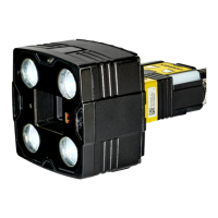
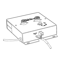
4. Attach the ground wire on the Strobe Control Cable to the threaded standoff on the
front of the Strobe Light Adapter using the supplied screw (Figure 2-3).
5. Locate the end of the Strobe Control Cable that terminates with exposed black and
white wires.
NOTE A two-pin terminal plug may already be attached to the Strobe Control cable. To use the trigger
input on the In-Sight camera you must remove this terminal plug and follow the remaining
instructions in this step. To use the camera without the built-in triggering input, leave the two-pin
plug attached to the Strobe Control cable, then insert the plug into pins 3 and 4 of the receptacle
on the back of the camera.
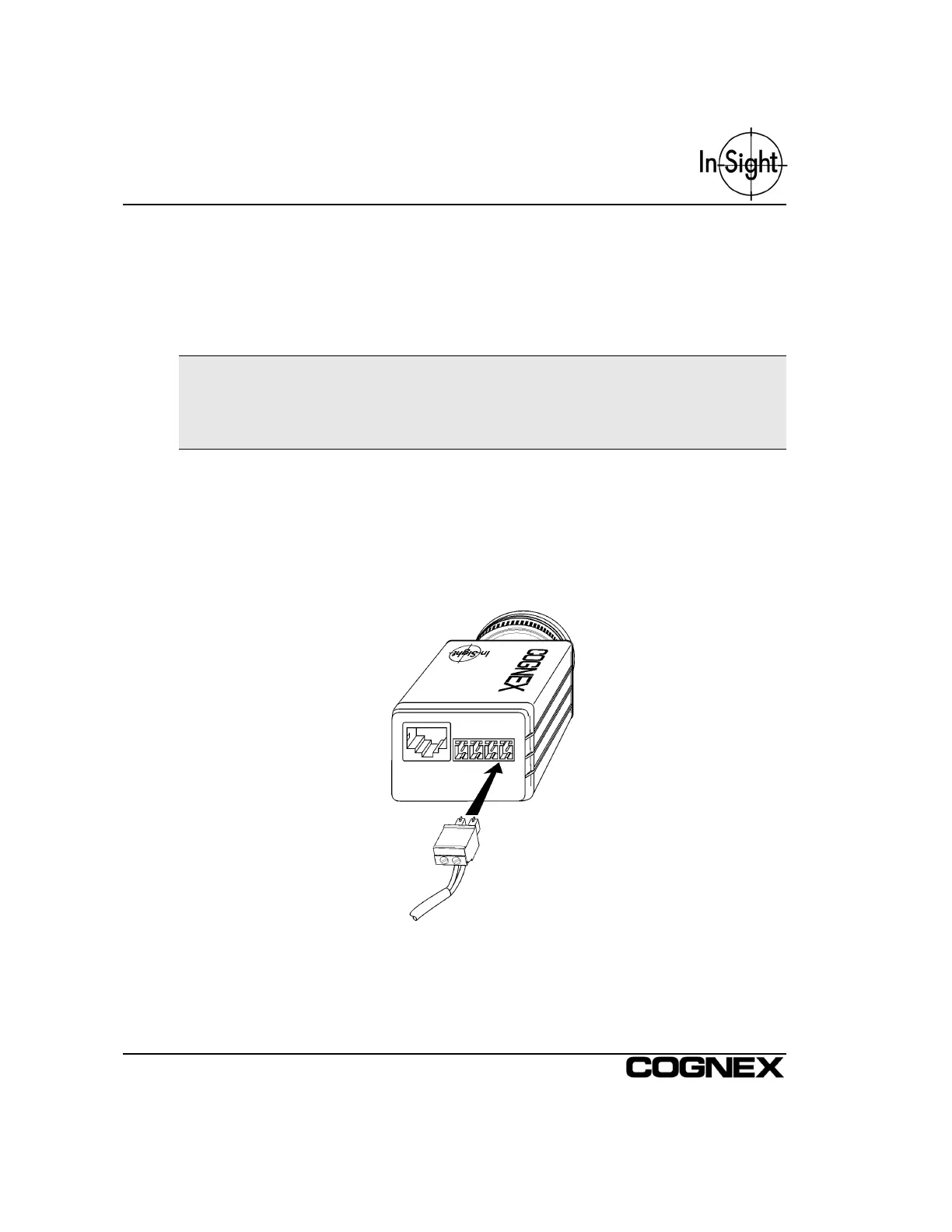
Insert the white wire into Pin 3 (Strobe +) of the terminal block plugged into the back of
the In-Sight camera. Using a small flat head screwdriver, secure the connection of the
white wire in the terminal block. Insert the black wire into Pin 4 (Strobe –) of the
terminal block on the In-Sight camera, using a screwdriver to secure the connection.
Refer to Installing the In-Sight 2000 or Installing the In-Sight 3000 for more detailed
information on the Strobe Output line on the In-Sight camera.
Figure 2-3: Connecting to the In-Sight Camera