259720-CTG-B-0108
Unitary Products Group 9
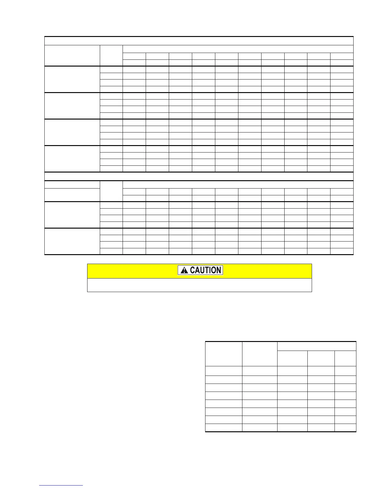
NOTE: Low cool (W1) airflow is 65% of high cool airflow.
NOTES:
1. Airflow expressed in standard cubic feet per minute (CFM).
2. Return air is through side opposite motor (left side).
3. In order to stay within the velocity rating the filters, airflows above 1800 CFM require either return from two sides or one side plus bottom.
4. Motor voltage at 115 V.
FILTER PERFORMANCE
The airflow capacity data published in the “Blower Perfor-
mance” table listed above represents blower performance
WITHOUT filters. To determine the approximate blower per-
formance of the system, apply the filter drop value for the fil-
ter being used or select an appropriate value from the “Filter
Performance” table shown.
NOTE: The filter pressure drop values in the “Filter Perfor-
mance” table shown are typical values for the type of filter
listed and should only be used as a guideline. Actual pres-
sure drop ratings for each filter type vary between filter manu-
facturer.
BLOWER PERFORMANCE CFM - COOLING
COOLING AIRFLOW WITH BOTTOM OR ONE SIDE RETURN
MODELS
Speed
Tap
EXTERNAL STATIC PRESSURE, INCHES W.C. (kPa)
0.1 0.2 0.3 0.4 0.5 0.6 0.7 0.8 0.9 1.0
CFM CFM CFM CFM CFM CFM CFM CFM CFM CFM
FC9M060B12UP11
FC9M080B12UP11
A 1650 1605 1570 1525 1465 1410 1350 1275 1170 1060
B 1165 1185 1175 1165 1150 1140 1100 1050 970 875
C 895 915 935 940 940 920 905 860 815 750
D 710 725 725 725 720 700 685 660 625 560
FC9M100C20UP11
A 2300 2210 2120 2020 1930 1830 1715 1595 1480 1350
B 1950 1900 1830 1755 1680 1595 1500 1390 1270 1155
C 1610 1545 1490 1440 1390 1315 1230 1155 1050 920
D 1325 1270 1225 1175 1105 1045 990 905 890 790
FC9M080C16UP11
FC9M100C16UP11
A 1960 1955 1925 1890 1830 1765 1695 1615 1600 1485
B 1565 1560 1560 1575 1545 1530 1475 1425 1365 1260
C 1230 1275 1285 1300 1310 1300 1280 1245 1190 1070
D 930 945 965 975 975 975 975 950 910 850
FC9M120D20UP11
A 2560 2485 2410 2320 2220 2135 2035 1920 1785 1650
B 2090 2050 1990 1970 1885 1820 1760 1675 1545 1405
C 1695 1675 1665 1615 1565 1510 1460 1385 1285 1140
D 1175 1150 1135 1110 1085 1055 1005 980 970 845
COOLING AIRFLOW WITH TWO SIDE RETURNS OR WITH BOTTOM AND ONE SIDE RETURN
MODELS
Speed
Tap
EXTERNAL STATIC PRESSURE, INCHES W.C. (kPa)
Input/
Airflow/Cabinet
0.1 0.2 0.3 0.4 0.5 0.6 0.7 0.8 0.9 1.0
CFM CFM CFM CFM CFM CFM CFM CFM CFM CFM
FC9M100C20UP11
A 2465 2380 2295 2195 2095 1995 1875 1760 1620 1470
B 2085 2035 1960 1880 1800 1705 1605 1485 1360 1235
C 1725 1625 1595 1540 1485 1405 1315 1235 1125 995
D 1420 1360 1310 1255 1180 1120 1070 970 950 845
FC9M120D20UP11
A 2615 2535 2450 2385 2285 2175 2075 1945 1825 1670
B 2055 2045 2015 1985 1932 1855 1785 1730 1605 1470
C 1690 1650 1620 1600 1570 1525 1470 1395 1300 1200
D 1345 1335 1335 1285 1250 1230 1180 1115 1010 850
Blower speed adjustments should be done by moving the COOL jumper on the control
board. DO NOT move the motor wires to different positions on the furnace control board.
FILTER PERFORMANCE - PRESSURE DROP INCHES W.C.
Airflow Range
Minimum
Opening Size
Filter Type
Disposable
Washable
Fibers
Pleated
CFM
in
2
In W.C. In W.C. In W.C.
0 - 750 230 0.01 0.01 0.15
751 - 1000 330 0.05 0.05 0.20
1001 - 1250 330 0.10 0.10 0.20
1251 - 1500 330 0.10 0.10 0.25
1501 - 1750 380 0.15 0.14 0.30
1751 - 2000 380 0.19 0.18 0.30
2001 & Above 463 0.19 0.18 0.30