12
VENT DAMPER INSTALLATION & INSTRUCTIONS
VENT SYSTEM MODIFICATION
should be corrected so the installation conforms with
the latest revision of the National Fuel Gas Code, ANSI
Z223.1. When resizing any portion of the common venting
system, the common venting system should be resized to
approach the minimum size as determined using the ap-
propriate tables in the latest revision of the National Fuel
Gas Code, ANSI Z223.
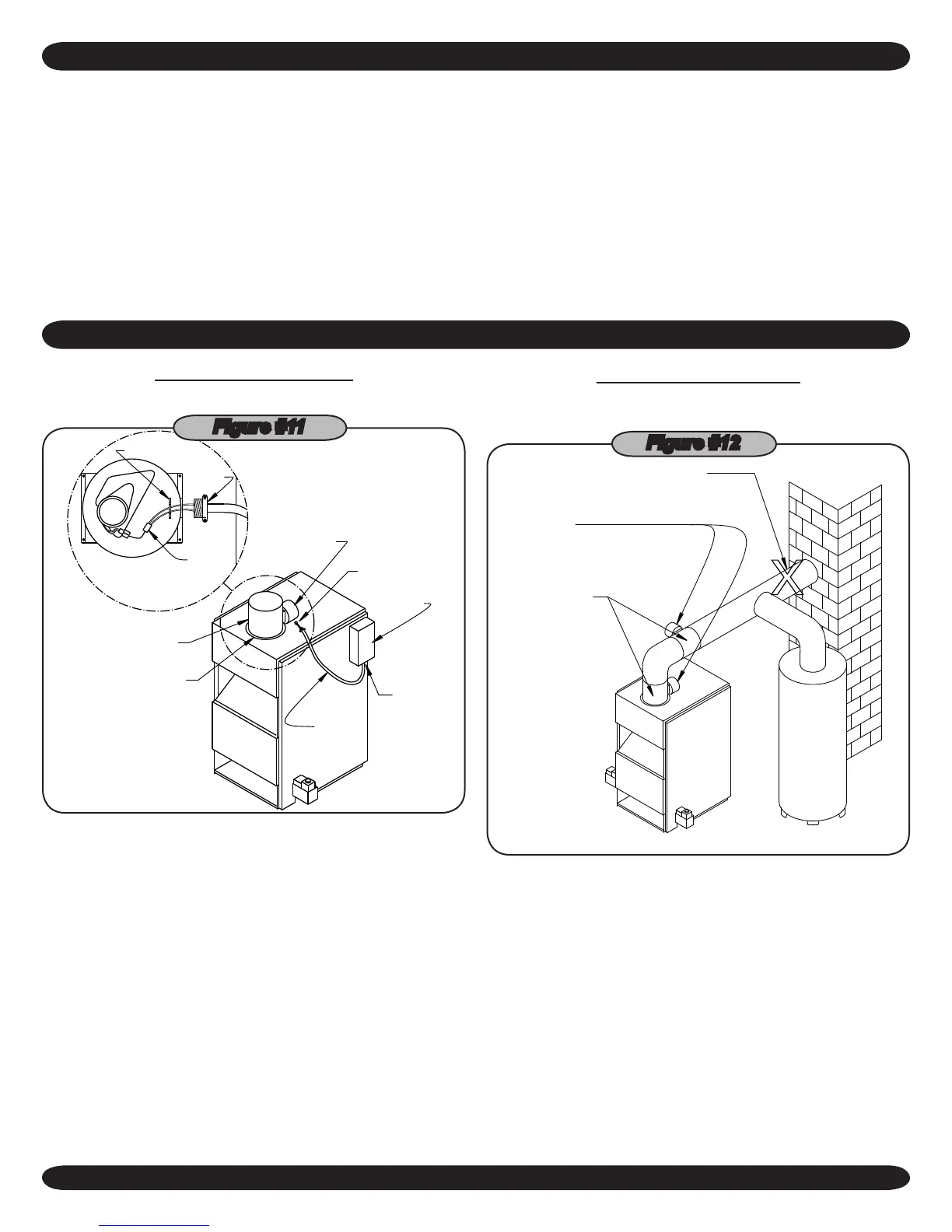
DAMPER INSTALLATION
NOTE: Refer to Figure #11 for steps 1-6.
LOCKNUT
HARNESS
CONN.
DAMPER
CONN.
INSTALLER
HOOK-UP
INSTALLER
HOOK-UP
DAMPER
MOTOR
DAMPER
DAMPER
WIRE
HARNESS
F A C T O R Y
WIRED
VENT OUTLET
AQUASTAT
VENT
Figure #11
Place Vent Damper on or as close to vent outlet of boiler
1.
as possible. (Figure #12)
Remove Vent Damper Motor cover.
2.
Feed damper wire harness connector through bracket
3.
hole on Damper Motor frame.
Tighten locknut onto Damper wire harness connector.
4.
Plug Damper connector into socket on Damper Motor
5.
frame.
Replace Damper Motor cover and wire Damper in accor-
6.
dance with Figure #11.
DAMPER INSTRUCTIONS
Ensure that only the boiler is serviced by the Vent Damp-
1.
er. (Figure #12)
ACCEPTABLE VENT
DAMPER LOCATIONS
UN-ACCEPTABLE
DAMPER LOCATIONS
BOILER
HOT WATER HEATER
CHIMNEY
INSTALLATION
POSITION OF DAMPER
X
MANUFACTURER'S
REFER TO DAMPER
INSTRUCTIONS FOR
CONTROL BOX
Figure #12
Clearance of not less than 6 inches between Vent
2.
Damper and combustible material must be maintained.
Additional clearance should be allowed for service of Vent
Damper.
Vent Damper must be in the open position when appli-
3.
ance main burners are operating.
The Vent Damper position indicator must be in a visible
4.
location following installation.
The thermostat's heat anticipator must be adjusted to
5.
match the total current draw of all controls associated with
the boiler during a heating cycle.
 Loading...