20
CHECKING GAS INPUT RATE TO BOILER
Gas input to the boiler can be adjusted by removing the
protective cap on the pressure regulator
(Figures #14-#16)
and turning the screw clockwise
to increase input and
counterclockwise
to decrease input. The manifold
pressures are taken at the outlet side of the gas valve.
(
Figure #15 and #16
) To check for proper ow of natural
gas to the boiler, divide the input rate shown on the rating
plate by the heating value of the gas obtained from the
local gas company. This will determine the number of cubic
feet of gas required per hour. With all other gas appliances
off, determine the ow of gas through the meter for two
minutes and multiply by 30 to get the hourly rate. Make
minor adjustments to the gas input as described above.
Burner orices should be changed if the nal manifold
pressure varies more than plus or minus 0.3 inches water
column from the specied pressure.
Primary air adjustment is not necessary, therefore air
shutters are not furnished as standard equipment. Air
shutters can be furnished on request where required by
local codes or conditions.
CHECK SAFETY CONTROL CIRCUIT after burner
adjustments are made for satisfactory operation.
1. Pilot: With main burner operating, turn the pilot
gas adjusting screw clockwise
until pilot gas
is turned off. (Figures #14-#16 on previous pages)
Within 90 seconds the main gas control should close,
shutting off the gas to the main burner.
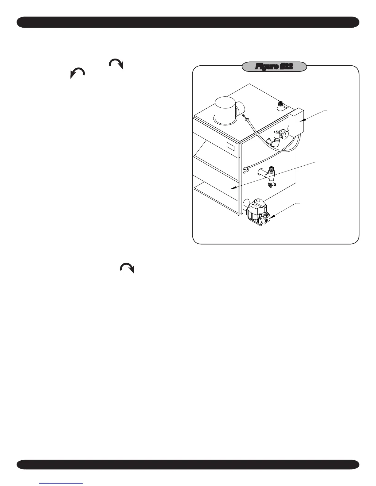
2. High Limit Control (Figure #22): Remove cover and
note temperature setting. Decrease this setting to
minimum and operate boiler. When the boiler water
temperature exceeds the control temperature setting,
the control will open the circuit, closing the automatic
main gas valve.
GAS VALVE
BURNER ACCESS
DOOR
HIGH LIMIT
AND OPERATING
CONTROL
Figure #22
 Loading...