19
GENERAL INSTRUCTIONS
With the paper still in place in the base, clean the top of
6.
the boiler castings of the boiler putty or silicone used to
seal between the castings and ue collector. Make certain
that chips are not lodged in the ue passageways.
When the cleaning process is complete, restore the boiler
components to their original position. Use IS-808 GE silicone
(available from a distributor) to seal around the ue collector
and boiler castings.
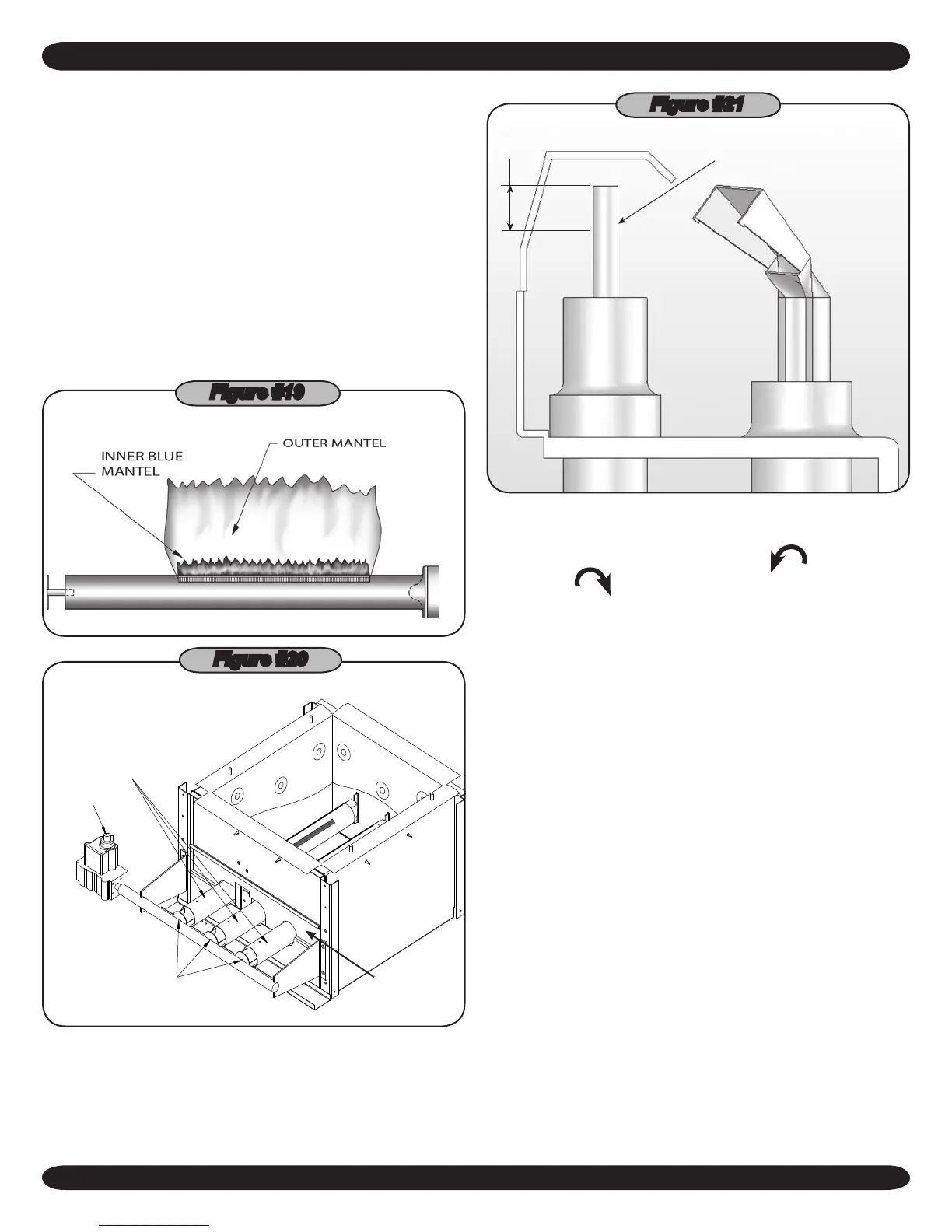
A visual check of the main burner and pilot ames should be
made at the start of the heating season and again in mid-
season. The main burner ame should have a well dened
inner blue mantel with a lighter blue outer mantel. Check the
burner throats and burner orices for lint or dust obstruction.
(
Figures #19 and #20
)
Figure #19
GAS VALVE
KNOB
ORIFICES
BURNERS
Figure #20
BURNER
DOOR
The pilot ame should envelop ⅜ to ½ inch of the tip of the
pilot thermocouple, ignition/sensing electrode or mercury sen-
sor. (
Figure #21
)
IGNITION ELECTRODE
3/8” TO 1/2”
IN FLAME
Figure #21
To adjust the pilot ame, remove the pilot adjustment cover
screw (Figures #14 - #16 on previous pages) and turn the
inner adjustment screw counterclockwise
to increase
or clockwise
to decrease pilot ame. Be sure to replace
cover screw after adjustment to prevent possible gas leakage.
The burners and pilot should be checked for signs of corro-
sion, rust or scale buildup. The area around the boiler must
be kept clear and free of combustible materials, gasoline and
other ammable vapors and liquids.
The free ow of combustion and ventilating air to the boiler
and boiler room must not be restricted or blocked.
It is recommended that a qualied service agency be em-
ployed to make an annual inspection of the boiler and heat-
ing system. They are experienced in making the inspections
outlined above, and, in the event repairs or corrections are
necessary, trained technicians can make the proper changes
for safe operation of the boiler.
 Loading...