18
NORMAL SEQUENCE OF OPERATION
On a call for heat, the thermostat will actuate,
completing the circuit to the control. The completed
circuit to the control will rst activate the circulator
and damper which will close an end switch inside
the damper. This action will complete the circuit to
the ignition system and ignition will take place.
In the event the boiler water temperature exceeds
the high limit setting on the boiler mounted high
limit control, power will be interrupted between the
control system and the ignition system. The power
will remain off until the boiler water temperature
drops below the high limit setting. The circulator
will continue to operate under this condition until
the thermostat is satised.
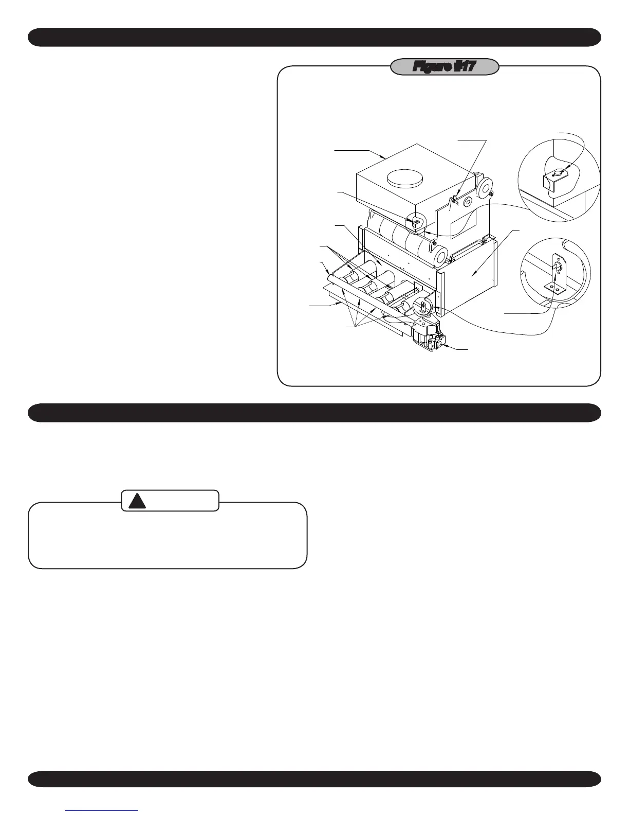
In the event the ow of combustion products through
the boiler venting system becomes blocked, the
blocked vent safety switch will shut the main burner
gas off. Similarly, if the boiler ueway becomes
blocked, a ame rollout safety switch will shut the
main burner gas off. (Figure #17) If either of these
conditions occur, DO NOT ATTEMPT TO PLACE
THE BOILER BACK INTO OPERATION. CON-
TACT A CERTIFIED SERVICE AGENCY.
BURNERS
ORIFICES
GAS VALVE
INTEGRAL DRAFT
HOLD DOWN
BOLT
BLOCKED VENT
SAFETY SWITCH
BURNER DOOR
BLOCKED VENT
SAFETY SWITCH
JACKET BASE
PANEL
ROLL-OUT SAFETY
SWITCH
MANIFOLD
BASE
HOOD
Figure #17
GENERAL INSTRUCTIONS
Before seasonal start-up, have a certied service agency
check the boiler for soot and scale in the ues, clean the burn-
ers and check the gas input rate to maintain high operating
efciency.
Label all wires prior to disconnection when
servicing controls. Wiring errors can cause
improper and dangerous operation.
CAUTION
!
Verify proper operation after service.
The service agency or owner should make certain the system
is lled with water to minimum pressure and open air vents, if
used, to expel any air that may have accumulated in the sys-
tem. Check the entire piping system and, if any leaks appear,
have them repaired.
Circulators need to be checked and maintained. Refer
to the circulator manufacturer's instructions.
The venting system should be inspected at the start of each
heating season. Check the vent pipe from the boiler to the
chimney for signs of deterioration by rust or sagging joints.
Repair if necessary. Remove the vent pipe at the base of the
chimney or ue and using a mirror, check vent for obstruction
and make certain the vent is in good working order.
The boiler ue gas passageways may be inspected by a light
and mirror. Remove the burner door. (
Figure #20
) Place a
trouble lamp in the ue collector through the draft relief open-
ing. With the mirror positioned above the burners, the ue gas
passageways can be checked for soot or scale.
The following procedure should be followed to clean the ue
gas passageways:
Remove the burners from the combustion chamber by
1.
raising the burners up from the manifold orices and pull-
ing toward the front of the boiler. (
Figure #20
)
Disconnect the vent pipe from the draft hood.
2.
Remove the top jacket panel.
3.
Remove the combination ue collector and draft hood
4.
from the boiler castings by loosening the nuts on the hold
down bolts located on each side of the collector. (
Figure
#17
)
Place a sheet of heavy paper or similar material over the
5.
bottom of the base and brush down the ue passage-
ways. The soot and scale will collect on the paper and is
easily removed with the paper.
 Loading...