Weekly equalize the battery pack.
If the vehicle is not operated daily the Power keyswitch should be turned off. This will power down the traction
control system and reduces power loss on the batteries.
Batteries in storage may self discharge and should be recharged when the specific gravity falls below 1.238 sp.
gr.
4.11 BATTERY REMOVAL AND INSTALLATION
Remove battery negative (-) cables.
Remove battery positive (+) cables.
Remove battery hold down.
Remove batteries from vehicle.
To install batteries, reverse the removal procedure with the negative (-) cables being attached last.
4.12 SINGLE POINT WATERING SYSTEM
When equipped, this is a single point watering system for maintaining a sufficient electrolyte level in the batteries.
NOTICE: Do not operate this system on brand new batteries. See Section 3.1 for the initial check on the
electrolyte level of new batteries. Complete 4 to 5 charge cycles before using the system.
System is to be used only after fully charging the batteries and batteries are warm.
The fill tube assembly which is used for adding water to the battery pack consists of a fill tube, one end having a filter
screen, the other having a female coupler and a rubber squeeze bulb.
Check the battery pack water level weekly by:
Inserting the fill tube filter end in an approved water supply.
Attaching the female coupler to the battery pack male coupler.
Squeeze the rubber ball until firm which indicates that filling is complete. Immediately disconnect the couplers
by depressing the push button on the female coupler. If the water supply is left connected after the filling
process is finished it could lead to an overfill.
4.13 ROLL OUT BATTERIES (IF EQUIPPED)
Before battery tray is removed check that the direction selector is in the neutral position, the power
keyswitch is in the “Off” position and the keys are removed.
A
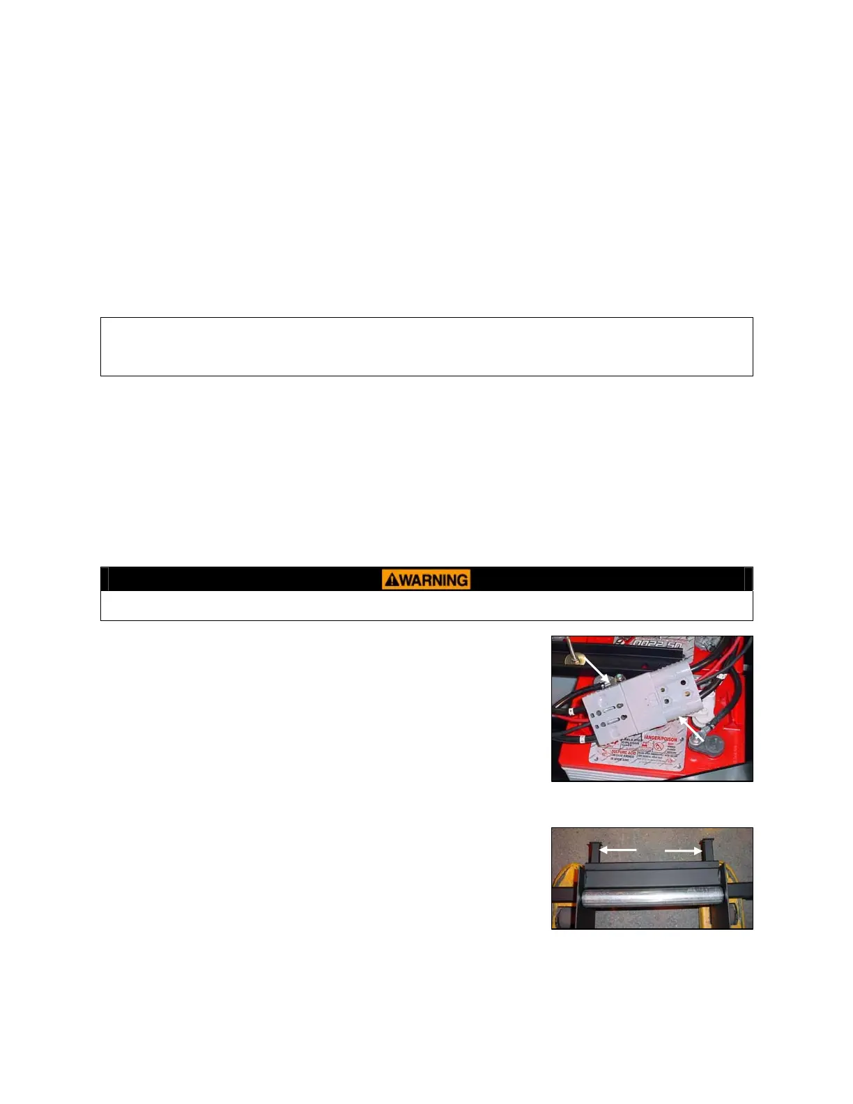
See Figure 4.13.1. Remove the rear deckboard and open the battery
compartment door. Disconnect the battery connector (Arrow A) from the
charger connector (Arrow B).
Positio
n battery connector in a location that will prevent pinching or damage to
the cables as the battery tray is moved.
Place a battery tray on a pallet jack
B
Move the jack w/tray under the vehicle frame so that it is centered on the
compartment door and under the vehicle frame.
Figure 4.13.1
Raise the jack so that the tabs (Figure 4.13.2 Arrow C) on the tray are behind
the vehicle frame. The tabs will prevent movement of the tray as the battery
pack is rolled out.
C
Figure 4.13.2
4-7
BC 2012