InteliLite Global Guide
26
It is necessary to ensure that potential difference between generator current COM terminal and battery “- ”
terminal is maximally ± 2V. Therefore is strongly recommended to interconnect these two terminals together.
Note: The controller should be grounded properly in order to protect against lighting strikes. The maximum
allowable current through the controller’s negative terminal is 4A (this is dependent on binary output load).
For the connections with 12 V DC power supply, the controller includes internal capacitors that allow the
controller to continue in operation during cranking if the batter voltage dip occurs. If the voltage dip goes during
cranking to 0 V and after 50 ms it recovers to 4 V, the controller continues operating. This cycle can repeat
several times. During this voltage dip the controller screen backlight can turn off.
Note: Recommended fusing is 3 A fuse.
Note: In case of the dip to 0 V the high-side binary outputs will be temporarily switched off and after recovering
to 4 V back on.
IMPORTANT: When the controller is power up only by USB and the USB is disconnected then the
actual statistics can be lost.
Note: Suitable conductor protection shall be provided in accordance with NFPA 70, Article 240.
Note: Low voltage circuits (35 volts or less) shall be supplied from the engine starting battery or an isolated
secondary circuit.
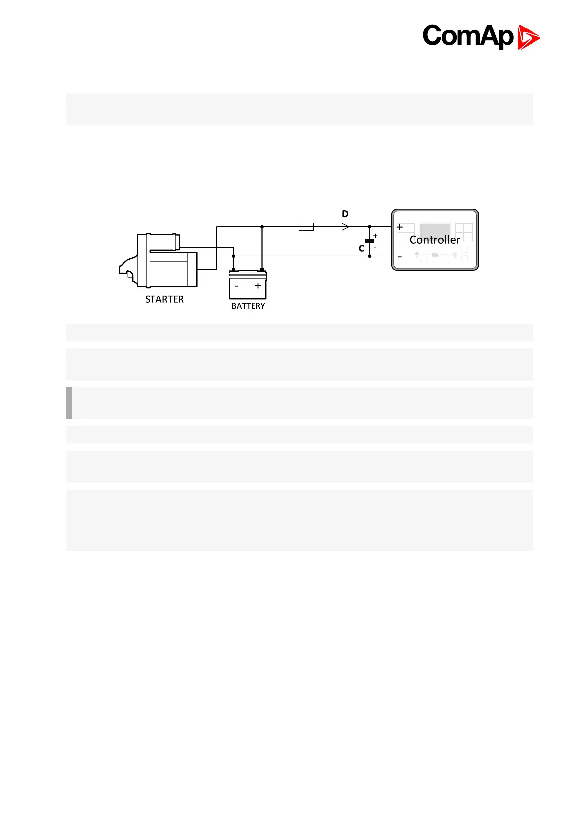
Note: It is also possible to further support the controller by connecting the external capacitor and separating
diode. The capacitor size depends on required time. It shall be approximately thousands of μF. The capacitor
size should be 5 000μF to withstand 150 ms voltage dip under following conditions: Voltage before dip is 12V,
after 150ms the voltage recovers to min. allowed voltage, i.e. 8V.
Power supply fusing
A 3 A fuse should be connected in-line with the battery positive terminal to the controller and modules. These
items should never be connected directly to the starting battery. Fuse value and type depends on number of
connected devices and wire length. Recommended fuse (not fast) type - T3 A. Not fast due to internal
capacitors charging during power up.