InteliLite
NT
– AMF20/25, SW version 2.2, ©ComAp – September 2014 35
IL-NT-AMF-2.2-Reference Guide.pdf
It is necessary to ensure that potential difference between generator current COM terminal and
battery “-” terminal is maximally ± 2V. Therefore is strongly recommended to interconnect
these two terminals together.
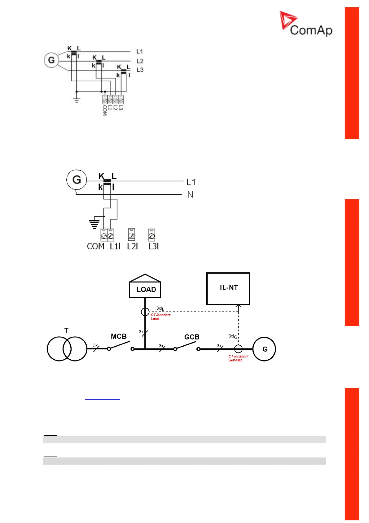
Single phase application:
Connect CT according to following drawings. Terminals L2l and L3l are opened.
CT location
There are two options of CT location.
a) Load
b) Gen-Set
New setpoint CT Location for AMF20 and AMF25 controllers is placed in group Basic Setting.
According to the connection it is possible to set CT location: Load or Gen-Set. When CT Location is
set to Load and MCB is closed the controller will display on Mains screen current value. The statistics
now contain Mains kWh, Mains kVArh, Genset kWh, Genset kVArh.
Hint:
The current measurement protections are active only when the Genset is running.
Hint:
If the CT Location is set to Load the Short Crct BOC protection is enabled only when GCB is closed.