InteliLite
NT
– AMF20/25, SW version 2.2, ©ComAp – September 2014 45
IL-NT-AMF-2.2-Reference Guide.pdf
Sensor Name: Name of used sensor, up to 14 letters can be used.
Dim: Name of measured unit (Bar, °C, %, …), up to 4 letters can be used.
Resolution: setting of resolution of measured value.
„0“ - e.g. 360 kPa, 100%, 50 C
„1“ – e.g. 360.0 kPa
„2“- e.g. 360.00 kPa
„3“ - e.g. 360.000 kPa
Set to: 1
When Analog input configuration is finished set the setpoints AI1 Wrn, AI1 Sd, AI1 Del in Engine
Protect group.
Each Analog input has separate triplet of setpoints: Wrn level, Sd level, AI del. Names of these
setpoints are fix defined
Number of decimal points of Wrn level and Sd level is the same as the configured number of decimal
points of measured value.
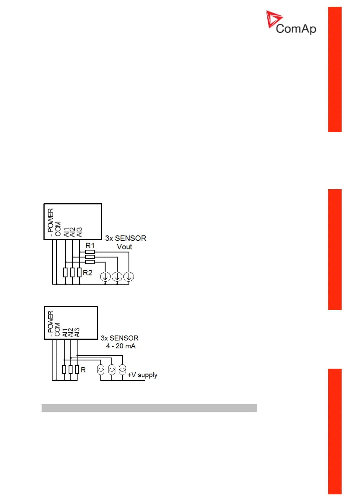
Analog input extension measurement (0 - 70V, 4 - 20mA)
On each analog input there is a possibility to connect voltage or current output sensor instead of
resistive one. Recommended wiring connection for these measurements are bellow.
Voltage output sensor - connection
Current output sensor – connection
Table with recommended values