Do you have a question about the ComAp MainsPro G99TT and is the answer not in the manual?
Explains symbols used in the document for notices, important procedures, and examples.
Describes the purpose of the guide and related documents like Installation and Application Guides.
Outlines terms of use, licensing, and intellectual property conditions for the manual.
Lists revisions, related software versions, dates of issue, and authors.
Explains the manual's role for installation and operation personnel.
Declares compliance with EC directives for safety and electromagnetic compatibility.
Important safety warnings and precautions for operation and setup.
Safety precautions regarding high voltage during measurement and terminal access.
Instructions for qualified personnel to check and adjust setpoints before initial operation.
Physical dimensions of the unit with diagrams and measurements.
Description of all unit terminals and their functions for connection.
Explains different wiring configurations for the unit's electrical connections.
Wiring diagram and settings for star connection of voltage measurements.
Wiring diagram and settings for delta connection of voltage measurements.
Guidance on connecting voltage transformers for measurement inputs.
Wiring diagram and settings for single-phase applications.
Details on connecting the unit's power supply terminals.
Wiring of relay outputs for safety and signaling functions.
Connection details for binary inputs used for control.
Details on voltage measurement ranges and their accuracy.
Examples of possible wiring configurations for the unit.
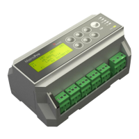
Identifies and describes the components on the unit's front panel.
Explains the function of each pushbutton for navigation and control.
Step-by-step guide to changing setpoints via the user interface.
Procedure to reset operation time and delete events.
Procedure to reset trip counters and clear statistics.
Steps to activate the unit's test mode for functional checks.
Procedure to restore the unit to its factory default settings.
How to secure setpoints using mechanical sealing to prevent changes.
Explains the meaning of different LED indicators for unit status.
Examples of displayed measurement screens for monitoring.
Interpretation of alarm messages shown on the homepage screen.
Explains the manual's role for application designers and engineers.
Describes the primary use of the relay for generator protection.
Lists various installations where the relay is used, e.g., Cogeneration, Microturbines.
Describes the typical steps for DNO-required utilization, from design to commissioning.
Defines TRIP as an event or status of the unit and its consequences.
Details what constitutes a TRIP event and its immediate effects.
Describes the unit's status during a TRIP and conditions for its termination.
Explains how to reset faults and the conditions required for a successful reset.
Compares voltage to thresholds, allowing 2 levels with independent delay.
Calculates floating average voltage over 10 minutes for overvoltage detection.
Compares frequency to thresholds, allowing 2 levels with independent delay.
Evaluates voltage symmetry using 3 independent methods.
Measures amplitude difference between any 2 phases.
Evaluates angle asymmetry via symmetrical components.
Fast Loss of Mains protection based on rotor displacement angle.
Explains the measurement principle of rotor displacement angle.
Fast Loss of Mains protection evaluating frequency instability.
Checks phase sequence and polarity for correct system configuration.
How the unit handles automatic return to mains after a fault.
Using binary signals for remote control and unit configuration.
Using external devices or systems for tripping the unit.
Using switches for manual fault reset operations.
Switching to alternative settings based on operational conditions.
Disabling protective functions when not required.
Confirming circuit breaker operation status.
Using counters for trip analysis and failure detection.
Details on the unit's timers for failure investigation.
Functionality for starting the unit into TRIP state upon power-up.
How to activate and use the TEST mode for phase-to-phase testing.
Explains the Reference Guide's content, including setpoints and technical information.
Details on measurement accuracy and response times under various conditions.
Defines the operating area for guaranteed measurement accuracy.
Accuracy and reaction time specifications for voltage measurement.
Accuracy and reaction time specifications for frequency measurement.
Accuracy specifications for the unit's time delay settings.
Reaction time specifications for Loss of Mains protection functions.
Key technical specifications including power supply, dimensions, and protection.
How the unit handles power supply interruptions and voltage drops.
Default configuration values for various setpoints.
Lists all available setpoints and their corresponding parameters and groups.
Details functions that can be assigned to the unit's binary inputs.
Lists and describes all available relay outputs and their functionalities.