Do you have a question about the ComAp InteliPro and is the answer not in the manual?
Details installation, wiring, settings, and user interface procedures for the InteliPro unit.
Provides detailed InteliPro functionalities and their practical application for designers and engineers.
Offers tips for wiring and setup of InteliPro communication interfaces for remote communication.
Contains library of setpoints, inputs, outputs, and technical data for detailed technical information.
States compliance with EC Low Voltage and EMC Directives, and specific standards like DIN V VDE V 0126-1-1.
Highlights critical safety precautions regarding relay outputs, binary outputs, and dangerous voltage.
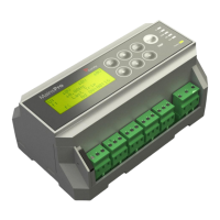
Lists the items included in the InteliPro package, such as the unit, relay card, holders, and terminal blocks.
Provides instructions for mounting the InteliPro unit onto a switchboard door, including cutout size.
Details wiring for voltage and current measurements, including warnings for safe handling of terminals.
Illustrates the complete measurement wiring scheme when using voltage transformers.
Illustrates the complete measurement wiring scheme when voltage transformers are not used.
Explains the use of binary inputs for receiving information, control, and alarm signaling.
Describes the use of binary outputs for signaling and control functions, including cautions for inductive loads.
Details the design for resistive sensors like VDO or DATCON, including wiring for grounded and isolated sensors.
Overview of the default plug-in module providing relay outputs and current measurement inputs.
Details the 2 NO relay contacts and their default function configuration for logical binary outputs.
Explains the two current inputs for Earth Fault and Ground Surge Current evaluation, emphasizing correct wiring.
Specifies the unit's design for 8-36 VDC power supply and recommendations for secure operation.
Shows typical wiring for InteliPro inputs/outputs, considering default configuration and trip outputs.
Describes using LiteEdit software to read, modify, and write configurations for InteliPro flexibility.
Explains how protective functions are provided as SW options unlocked by a software dongle.
Details basic operation using up/down/menu/enter buttons for navigation and setpoint adjustment.
Describes the 3 levels of password protection for securing setpoints and unit access.
Explains the meaning of the 5 LEDs (Status, CB1, CB2, TRIP) for indicating InteliPro operational status.
Describes the essential mode using a common trip output for the main connection device (MCB).
Details operating two circuit breakers, assigning functions to Trip 1 and Trip 2 outputs.
Explains how CB1 and CB2 can act as backups for each other based on setpoint configuration.
Defines TRIP events, status, and consequences like output activation and history recording.
Explains how fault reset is triggered by buttons, inputs, or automatic settings, and its conditions.
Describes interconnecting InteliPro with IG/IS-NT controllers via CAN2 bus for data transmission.
Explains how to configure binary and analog values transmitted from InteliPro via CAN2 communication.
Explains the autonomous nature of protective stages, their activation, and setpoint assignment.
Details how to assign appropriate trip outputs (Trp 1, Trp 2) to specific protective stages.
Describes using LiteEdit to set blocking conditions for individual functions via a matrix or binary inputs.
Compares measured voltage to limits, with hysteresis, for over/undervoltage detection and tripping.
Compares frequency to limits, with hysteresis, for over/underfrequency detection and tripping.
Evaluates amplitude difference between phases against a preset voltage unbalance limit.
Detects loss of mains using Vector Shift or Rate Of Change Of Frequency methods.
Covers definite-time and IDMT overcurrent stages for detecting and tripping on overcurrent events.
Detects fault location based on current direction, sensitive to angle zones for tripping.
Monitors neutral voltage rise in systems with isolated or indirectly grounded zero-points for ground faults.
Covers Synchro Check, AC Reclosing, Pole Slip, Dynamic Grid Support, and QU protection.
Explains interconnecting InteliPro via RS485 and CAN2, detailing bus parameters and rules.
Provides guidelines for CAN bus connection, including topology, length, and termination resistors.
Details RS485 connection requirements, including termination, cable type, and surge protection recommendations.
Describes the RS232 module with modem signals for connecting to COM1.
Details the dual-port module with independent RS232 (COM1) and RS485 (COM2) interfaces.
Explains the USB slave port module for easy service connection, requiring FTDI driver installation.
Describes the analog input/output extension module with configurable analog inputs and one analog output.
Outlines three connection possibilities: Direct PC, Dynamic IP/AirGate, and Static IP for IB-Lite.
Covers controller identification, CT/PT ratios, nominal voltage, frequency, and power settings.
Details communication settings including COM modes, Modbus speed, CAN bus mode, and IP addressing.
Defines how to configure binary inputs for alarm signaling, including input name and alarm type.
Explains configuring binary inputs for specific functions like breaker feedback or control inputs.
Details alarm types like Warning, Comm Trp, Trp 1, Trp 2, and Trp 1+2 for binary inputs.
Describes how CB1 and CB2 feedback inputs indicate breaker status and detect failures.
Covers F.R. Button, DC TripCircuit, Access Lock, and Ext MF Relay inputs for control and monitoring.
Details Common Alarm, Comm Trp, !Comm Trp, Bak Comm Trp, Del Comm Trp outputs and their logic.
Explains Trp 1, Trp 2, and their backup/inverted variants for assigning trip signals to protection stages.
Describes outputs like U<> Prot, U< Prot, U> Prot, f<> Prot for signaling voltage and frequency protection status.
Covers signals for NVD, EFC, IGS, DOC, P, I>, and other protection functions.
Details signals for DC Healthy, Watchdog, Ctrl HeartBeat, MaxParTime, and various measurement statuses.
Explains outputs for CB protection, Mains OK, Average Voltage, Pole Slip, Dynamic Voltage, and general alarms.
Sets nominal mains voltage (Ph-N, Ph-Ph), frequency, power, and current feeder parameters.
Configures controller address, communication modes (DIRECT, MODBUS), modem strings, and speeds.
Configures IP address, NetMask, Gateway, DHCP, and APN settings for Ethernet and GPRS communication.
Includes protection activation delays, automatic fault reset, and priority switching configurations.
Defines thresholds and delays for overvoltage, undervoltage, unbalance, and average voltage protections.
Sets thresholds, delays, and hysteresis for overfrequency and underfrequency protections.
Configures Vector Shift and ROCOF protection parameters for detecting mains failure.
Covers definite-time, IDMT, and voltage-controlled overcurrent settings and curve selections.
Details settings for Earth Fault (ANSI 50N, 51N) and Ground Surge Current (ANSI 50GS, 51GS) protections.
Configures directional overcurrent, directional power, and phase rotation protections.
Sets parameters for Synchro Check, AC Reclosing, and Pole Slip protections.
Configures protection settings for CU and IOM analog inputs, plus SMS/E-mail notification options.
Provides a comprehensive list of all possible alarm messages generated by the InteliPro unit.
Lists measured mains parameters including frequency, phase voltages, currents, and phase angles.
Details measured mains power parameters: active, reactive, apparent power, and power factor.
Lists values from extension modules, energy consumption statistics, and date/time information.
Details EMC test descriptions, compliant standards, and test conditions/levels for the InteliPro unit.
Provides technical details on power supply range, drop-out immunity, and consumption.
Specifies operating temperature range, humidity, protection degree, and vibration/shock resistance.
Lists the physical dimensions, weight, and mounting cutout size of the InteliPro unit.
Lists electromagnetic compatibility and low voltage directive standards the unit complies with.
Details characteristics of binary inputs, including number, insulation, pole, and voltage levels.
Provides specifications for binary outputs: number, insulation, type, operating voltage, and switching current.
Details analog input characteristics like number, insulation, electrical range, resolution, and sensor types.
Specifies measurement inputs, types, voltage/current ranges, accuracy, and frequency range for mains.
Details measurement specifications for Neutral Voltage Displacement and Sync Check functions.
Lists interface options: RS232, RS485, USB, and Ethernet, including baud rates and bus lengths.
Specifies the relay outputs, operating voltage, max switched voltage/current, and current measurement inputs.