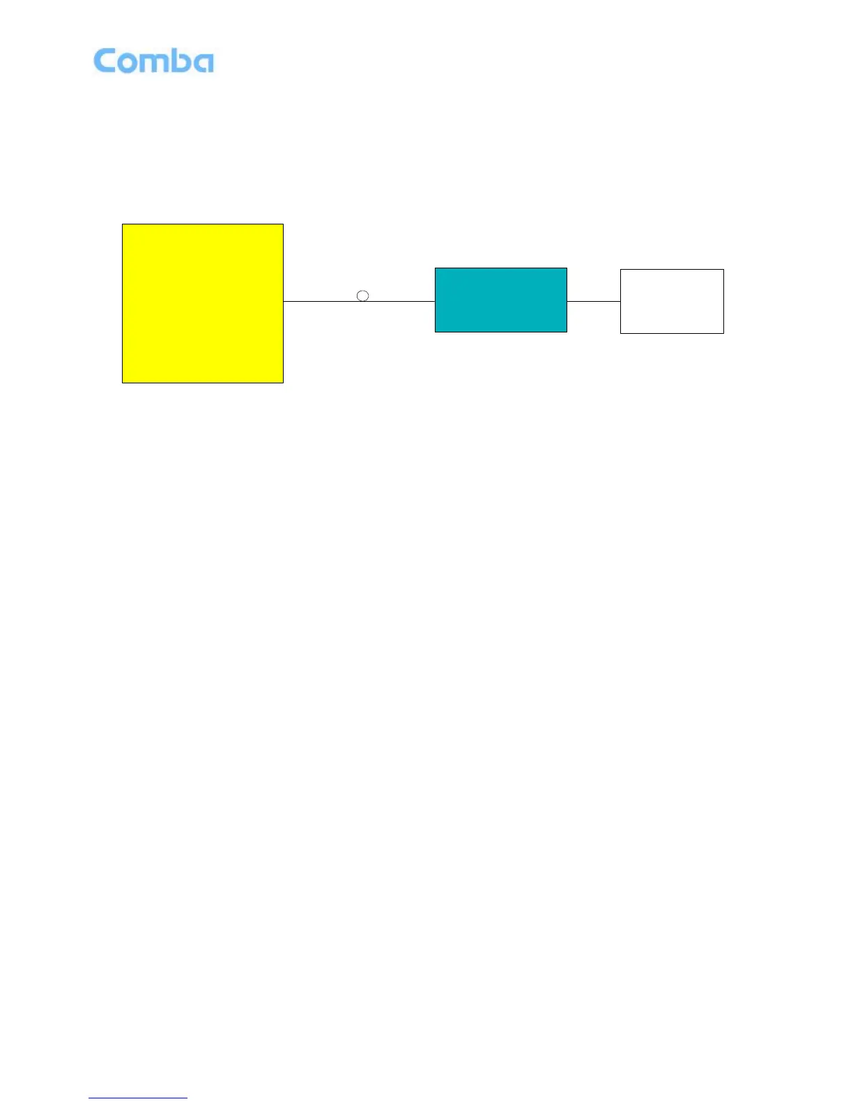
Figure 5: System Diagram
On the DL, signals from the BTSs converted into optical signals after amplification in the MU.Then the
optical signals are transmitted to the RU via optical fiber. The Optical TX/RX Module of RU converts the
DL optical signals into RF signals. After amplification, the signals are transmitted at the MT port to the
service antenna.
On the UL, the signals transmitted by the mobile are converted into optical signals, and then via the UL
optical fiber. The signals are transmitted to MU, which then converts the optical signals back to RF
signals.