USER MANUAL FOR RA-7E00 III3
Copyright - refer to title page
3.4 EQUIPMENT CONNECTORS
RA-7E00 is designed for all cables entries from the bottom of the enclosure. The figures below present the
connectors of RA-7E00.
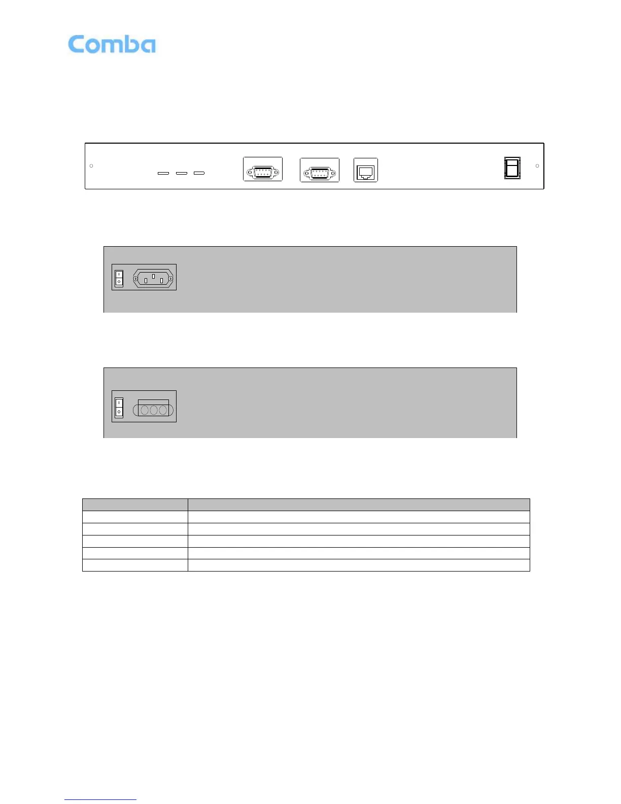
Figure 19: MU Front Panel Connectors
AC 100V-240V 50Hz/60HzBATTERY
Figure 20: Rear Panel Connectors (AC 110~220V in)
Figure 21: MU Rear Panel Connectors (DC-48V in)
Table 5: MU Connections
A power supply cable for power supply
OP uplink/downlink SC/APC optic connector.
DB15 female connector, Modem expansion port.
RJ45 Ethernet connector, OMT commissioning port.
DB9 female connector, reports alarm to BTS.