Do you have a question about the Comelit 4681 and is the answer not in the manual?
Product for audio/video communication systems in residential, commercial, industrial, and public buildings.
Activities by qualified personnel, following manual indications for proper installation.
Disconnect power before wiring; use suited wires; avoid shared ducts with power cables.
Observe manual indications; ensure system integrity to prevent tampering or damage.
Routine cleaning only; repairs by Comelit or qualified personnel; avoid aggressive products.
Comelit not responsible for non-intended use or failure to follow manual instructions.
Manufacturer declares conformity to applicable directives; full EU declaration on web page.
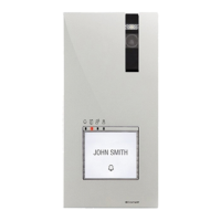
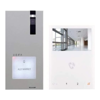
Colour audio-video module for Comelit 'Building Kit' 2-wire systems, used with riser power supply Art. 1210.
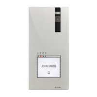
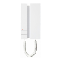
Audio module for remote colour PAL camera, compatible with Comelit 'Building Kit' 2-wire systems.
Identifies DIP switches, buttons, connectors, LEDs, speaker, microphone, and camera for the module.
Details terminal block connections and cable usage for remote camera connection.
Lists main specs: system compatibility, camera, video encoding, resolution, illumination, and humidity.
Lists main specs: system compatibility, microphone, loudspeaker, and humidity.
Recommended height (160 cm) and angle (100°) for camera installation, avoiding direct light sources.
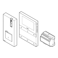
Illustrates frame connection, module insertion, and wiring for physical installation of the external unit.
Shows specific connection diagrams for Art. 4681 and Art. 1621VC modules to the external unit.
Details selection options (WHITE, OFF, BLUE) for the nameplate LED lighting.
Illustrates module assembly, microphone connection, and securing the external unit housing.
Diagram showing standard connections for Art. 4681/1621VC with lock-release and door open signals.
Illustrates connections for Art. 4681/1621VC with an additional power supply unit (Art. 1595).
Details cable usage for powering the camera from the external unit or a separate supply.
Shows wiring for using the external unit's relay with a 230V or 12V/24V AC-DC supply.
Illustrates wiring for connecting a safety lock, showing contact options.
Explains the function of JP1 for relay activation based on actuator commands.
Provides a table detailing the power consumption of various external unit modules.
Explains system current limits (100mA) and when to use supplementary power supply Art. 1595.
Shows how to connect button modules (33433, 33434, 33436, etc.) to Art. 4681/1621VC.
Illustrates the wiring diagram for connecting Art. 3348B and 3348BM modules.
Provides the connection diagram for Art. 3360B and 3360BM modules.
Shows how to connect Art. 3064S and Art. 1172B modules, including limits and polarity.
Details wiring for Art. 3064S and 1172B when using an additional power supply (Art. 1595).
Illustrates the wiring diagram for connecting Art. 3188A to the system, including power supply.
Shows the wiring for Art. 3070S and 3072S, including cable details and power supply.
Diagram for connecting Art. 3063D, showing limited connections and use of Art. 1172B.
Illustrates wiring for Art. 3063D with an additional power supply (Art. 1595), detailing limits.
Shows how to connect SK9015 for readers Art. SK90001 and SK90011, including limits.
Illustrates steps for programming button modules, including DIP switch settings for user codes.
Shows visual steps for setting DIP switches on modules for various programming functions.
Sets module as main external unit by default; set DIP switches to ON for secondary unit.
Explains busy tone meaning communication with another external unit is in progress.
Provides guidance on system performance and layouts for Building Kit audio/video systems.
| Brand | Comelit |
|---|---|
| Model | 4681 |
| Category | Intercom System |
| Language | English |