5
ON DIP
PR
ON
OFF
J11 CNF J9
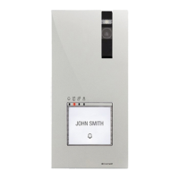
11.
12.
13.
1. 2.
3.
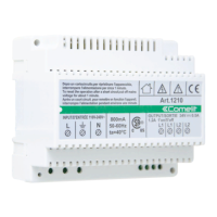
1621VC
12 V
MAX 150 mA
1621VC
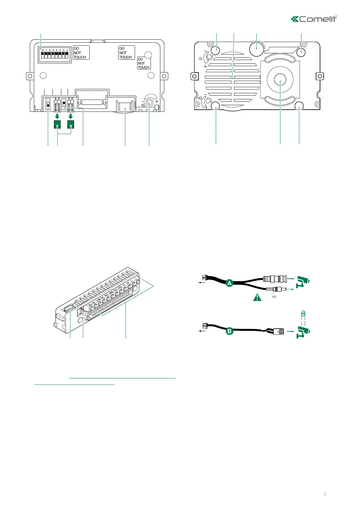
1. S1 DIP switches for function programming and setting
the user code.
2. PR switch for input/output programming.
3. J11 and J9 jumper for power supply management.
Remove both in the case of a separate power supply.
4. CNF switch for confirming special programmes.
5. The connector is reserved for module 1621VC, for the
connection of the remote camera.
6. Loudspeaker volume control.
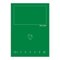
7. Indicator LED: call sent.
8. Speaker.
9. Microphone.
10. Indicator LED: system busy.
11. Indicator LED: sound activated.
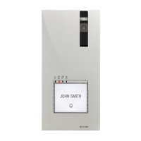
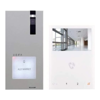
12. Colour camera (with Art. 4681 only).
13. Indicator LED: lock-release activated.
1. 8-pole cable connector.
2. JP1 RC network management for door lock filter on relay
contacts (see “Variant for using the external unit relay/
Variant for using a safety lock”).
3. Terminal block for connection:
SE+ SE- electric lock connection
COM common relay contact
NC normally closed relay contact
NO normally open relay contact
GND input reference negative for DO-RTE
DO door opened signal input
RTE local lock-release input
V- power supply negative
V+ power supply positive
LL bus line connection
Cables for remote camera connection (Art.
1621VC only)
Use cable A to power the camera from the external unit (12V-
150 mA MAX).
Use cable B if the camera is powered separately.