EasyManuals Logo

CommScope ION-M7P User Manual

CommScope ION-M7P
50 pages
To Next Page IconTo Next Page
To Previous Page IconTo Previous Page
Page #23 background imageLoading...
Page #23 background image
3 Commissioning
Page 23
3.2.2. Connections
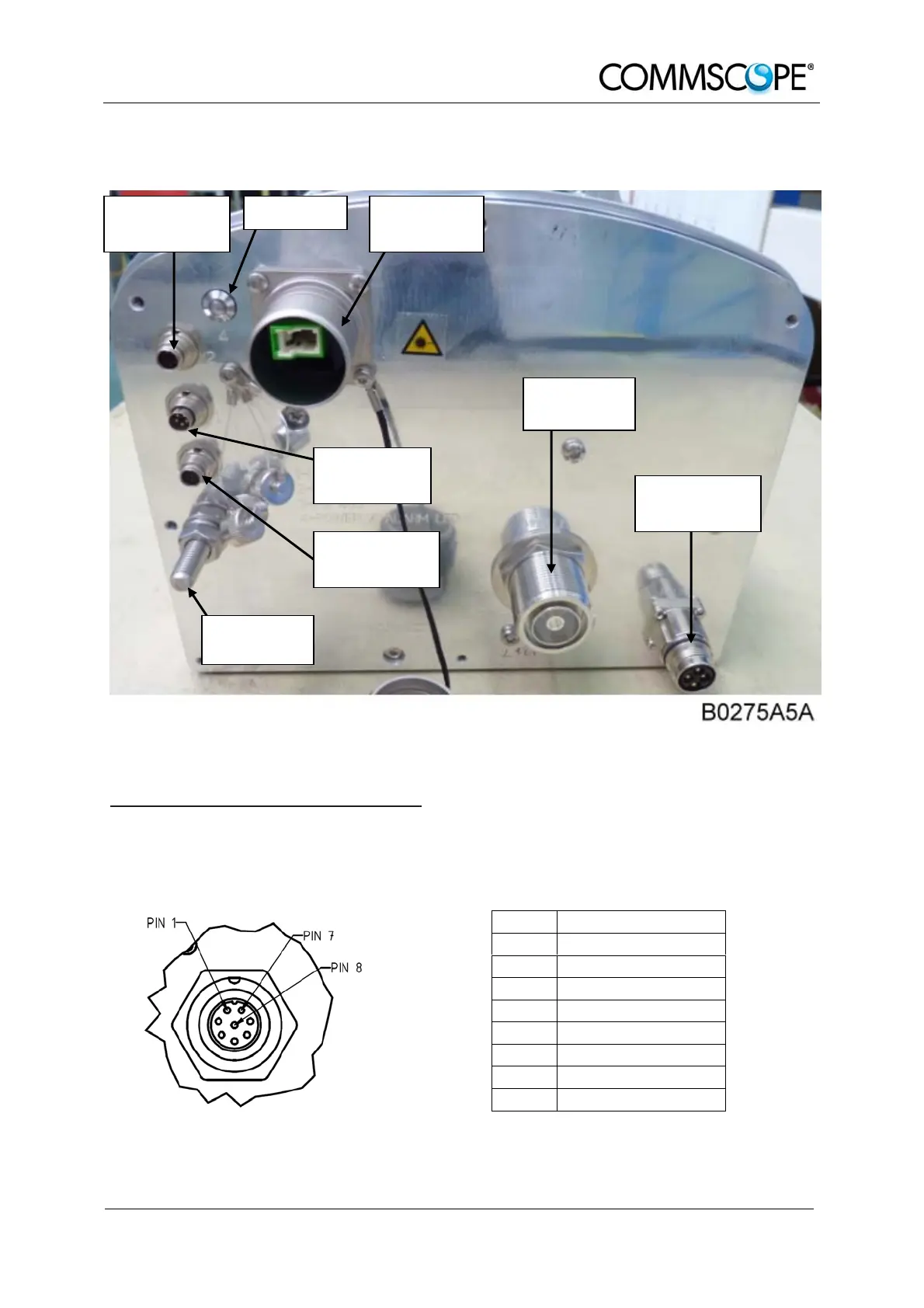
figure 3-4 Connector flange of ION-M7P/85P/17P/19P
Control Connector (RS485 / RS232)
This 8-pin male connector (type: Binder Series 712) primarily supports control of the
Extension Unit via RS485 bus.
PIN Assignment
1 not connected
2 RS232 Rx
3 RS232 Tx
4 not connected
5 GND (RS232)
6 RS485 R+/D+
7 RS485 GND
8 RS485 R-/D-
figure 3-5 RS485 connector table 3-2 RS485 connector, pin assignment
Alarm output Status LED Optical-fiber
connector connector
Antenna
connector
Alarm input
connector
Power supply
connector
RS485 / 232
connector
Grounding
bolt

Other manuals for CommScope ION-M7P

Questions and Answers:

Question and Answer IconNeed help?

Do you have a question about the CommScope ION-M7P and is the answer not in the manual?

CommScope ION-M7P Specifications

General IconGeneral
BrandCommScope
ModelION-M7P
CategoryRemote Control
LanguageEnglish

Related product manuals