3 Commissioning
Page 25
To minimize passive inter-modulation (PIM) distortion, attention has to
be paid to the physical condition of the connector junctions. Do not use
connectors that show signs of corrosion on the metal surface. Prevent
the ingress of water into the connector. Attach and torque the
connectors properly.
3.4. POWER CONNECTION
Before connecting electrical power to the units, the system must be grounded as
described in the previous chapter.
Mains power must be connected at the power supply connector of the unit (see
chapter 3.2.2 Connections).
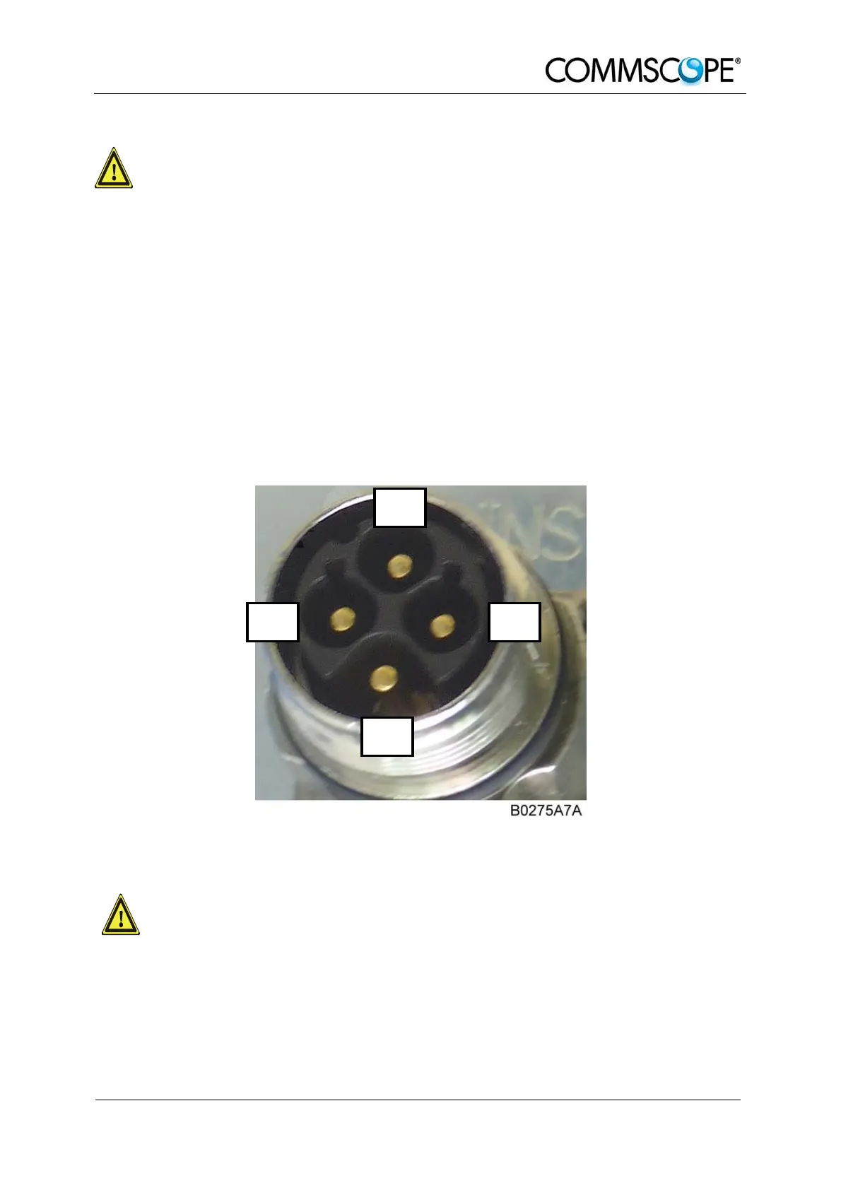
The power supply plug is part of the delivery. The correct wiring of the power supply
plug is as follows:
N
n.c.
PE
L
figure 3-8 AC power supply plug
For the AC power supply connection, a minimum cross section of 1.5
mm
2
is required. Each wire must observe the applicable national
regulations regarding loop impedance, voltage drop, and methods of
installation. Make sure to connect the correct voltage to the unit.
) Note: Do not connect or disconnect the power cord at the power supply
connector while power is on. Turn off mains power * before
connecting the power cord at the Remote Unit, then, engage mains
power again.