User’s Manual for
ION™-M7P/85P/17P/19P (ML-Cab)
Page 40 MF0143AUA.doc
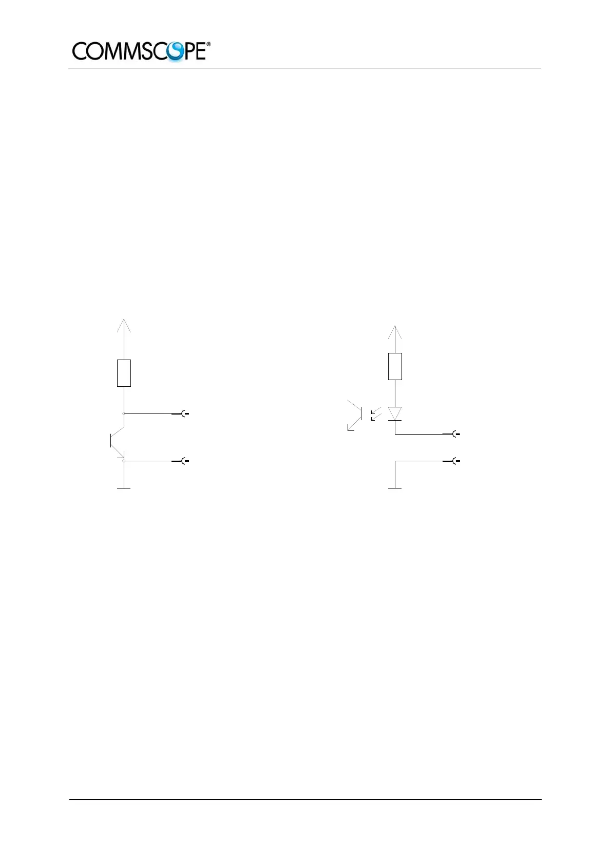
With the external alarm inputs it is possible to monitor the status of connected
devices, e.g. a UPS, via software. All alarm inputs are normally high (5 V) without
connection. The polarity (high/ low) can be set via the software at the Master Unit (for
details please see according software manual).
The device to be monitored must be connected so that the alarm contacts will be
closed in case of an alarm (I max = 8 mA). The alarm inputs are potential-free with
common ground.
Subminiature circular connectors series 712 with five and seven contacts, which are
contained in the alarm kit, can be ordered directly from the Binder Connector Group,
the manufacturer, or indirectly from Andrew Solutions. For the designation of the
alarm kit see chapter 6.3 Spare Parts.
V1651A1
Alarm output
Alarm GND
Alarm GND
Alarm GND
Alarm GND
Alarm input
ION-M alarm outputs
4700R
+5 V
ION-M alarm inputs
+5 V
560R
figure 4-3 Alarm inputs and outputs, standard
4.6. TROUBLESHOOTING
The status of the Remote Unit can be checked via the Master Unit (for details please
refer to the software manual of the Master Controller). Locally, the status can be
checked at the LED, see chapter 4.4 Status LED Alarms.