ERA® WCS and e-POI Subracks and Power Supply Unit Installation Guide M0201ABK_uc
Page 16 © June 2021 CommScope, Inc.
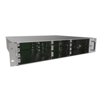
WCS-2 and WCS-4 Subrack Overview
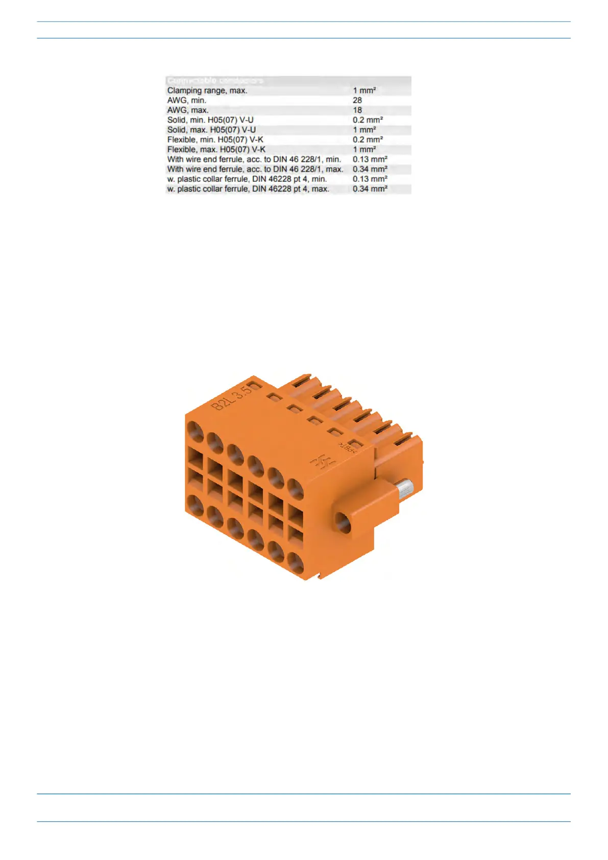
Before inserting the external alarms connector into the WCS alarms port, insert the conductors carrying the
alarm signals into the alarm connector (circular holes). The alarm connector provides tension clamp
connections in the mating connector. The wires carrying the alarm signals should be stripped back by 7mm
and then inserted into the alarm connector. The alarm wires can range from sizes 18 AWG – 28 AWG,
(0.2 mm
2
to 1 mm2).
Typically, the alarm wires are connected to the mating connector first, then the mating connector is plugged
into the alarm connector on the back panel of the WCS and screwed into place.
Mating alarm connector