M0201ABK_uc ERA® WCS and e-POI Subracks and Power Supply Unit Installation Guide
© June 2021 CommScope, Inc. Page 41
Optional e-POI Subracks
Interface Card (IFC)
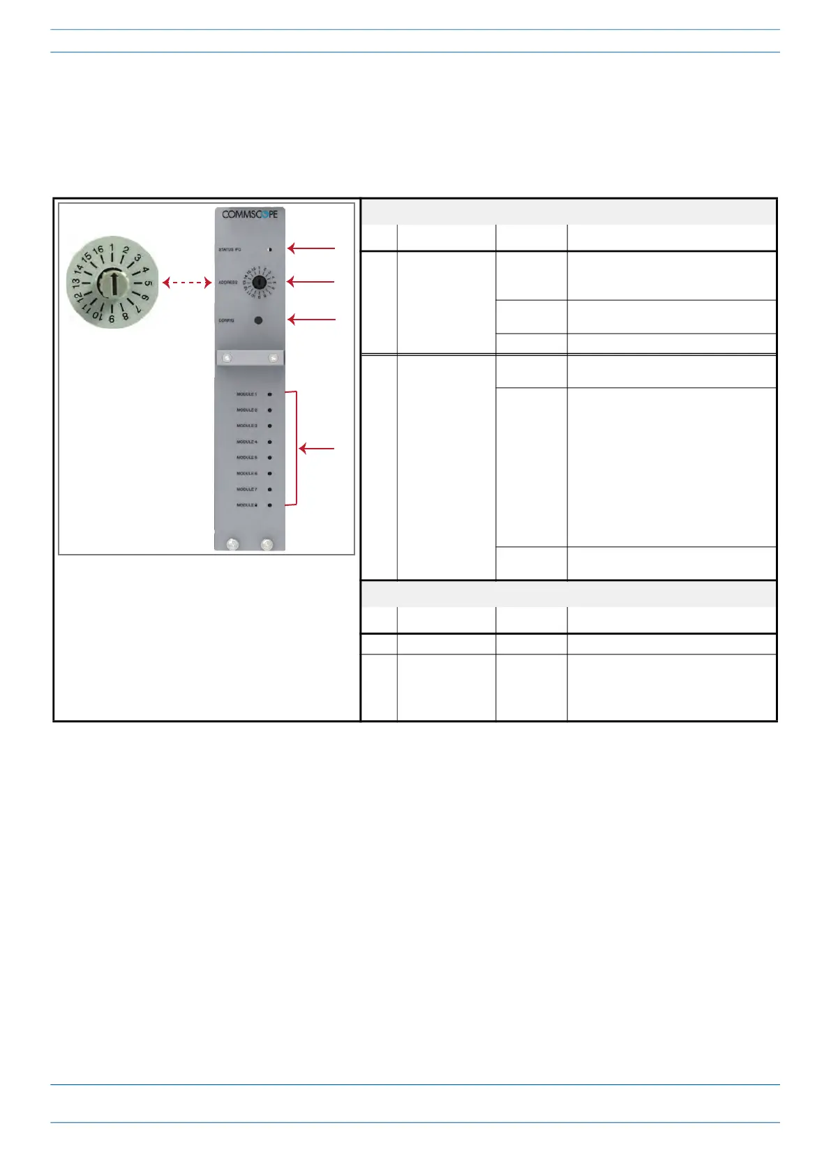
The IFC (PN 7676260-xx) is used to set the Subrack number of the e-POI Subrack. It also provides
communications, status, and alarms for the e-POI Modules installed in the e-POI Subrack.
The following graphic and table identify the IFC Card LEDs and connectors.
IFC LEDs
Ref # LED LED Color Description
1 Status
• Off
• The e-POI Subrack or the IFC is not
fully seated or is not receiving
power.
• Green
• e-POI Subrack or IFC is functioning to
specification.
• Red • Active alarm on e-POI Subrack or IFC.
4 e-POI Module
Status 1 - 8
• Off
• e-POI Module in corresponding slot
is not receiving power.
• Green
• e-POI Module in corresponding slot
is functioning to specification. e-POI
Module Status LED must be green
before connecting corresponding RF
signals to input.
NOTE: If e-POI Module is not
functioning, PIM or VSWR
rating could be
compromised, causing an
alarm on the BTS.
• Red
• e-POI Module in corresponding slot
has active temperature alarm.
IFC Connectors
Ref # Component Device Function
2 Address switch Rotary dial Must be set to 1.
3 Config button Pushbutton Alerts ERA Software to scan for and
remove references to removed RFD
Cards; see "Removing an e-POI Module
from an e-POI Subrack” on page 80.