M0201ABK_uc ERA® WCS and e-POI Subracks and Power Supply Unit Installation Guide
© June 2021 CommScope, Inc. Page 51
Install the Subracks and PSU in an Equipment Rack
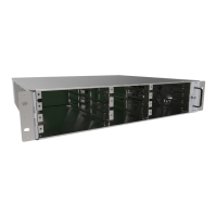
Figure 9. Power Supply Unit DC Output Terminal Lugs
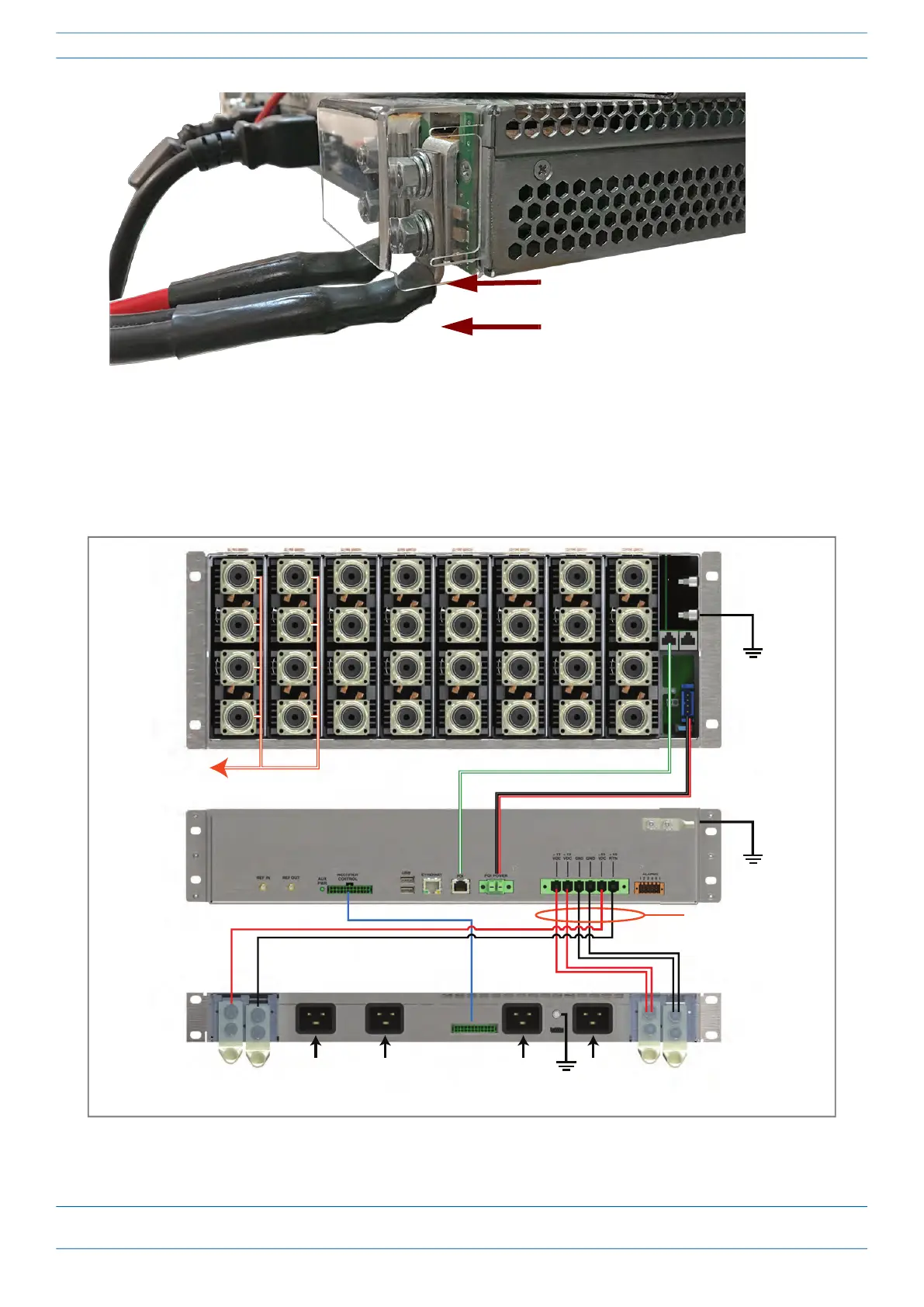
Connect the WCS Rear-panel Cables
1 Connect the rear-panel power, communication, and control cables as shown in the following graphic.
Figure 10. WCS Rear Panel Cabling
DC Output terminal lugs extend ~
0.5 inch (13 mm) below subrack.
Avoid contact with exposed metal
on terminal lugs.
e-POI
WCS
PSU
To/From eNodeB
e-POI communicaons
e-POI power
Subrack ground
(required)
WCS DC power
Subrack ground
(required)
Recfier control
Subrack ground
(required)
85 to 264 Vac