20
15. RUDDER POSITION
16. RUDDER COMMON
These three terminals connect to the
rudder follower. With the cable from the
distribution box unplugged from the rear
of the autopilot, and the rudder turned to
dead ahead, the resistance between
RUDDER POWER and
RUDDER POSITION, and RUDDER
POSITION and RUDDER COMMON
should be equal, and each measure
approximately 600 ohms if you are using
a ComNav Rudder Feedback.
17. NAV SIGNAL
18. NAV RETURN
These two terminals connect to the
NMEA 0183 output of a Loran C
Receiver, GPS Receiver, or other type of
navigation device so equipped. Whenever
the autopilot is turned on, the LED next to
these terminals will light while data is
being received.
19. RAI SIGNAL
20. RAI RETURN
These two terminals are used to run up to
three ComNav Marine rudder angle
indicators. Multiple rudder angle indicator
installations must be wired in series. If all
the indicators move to port when the
rudder is moving to starboard, reverse the
connections to these terminals. If only
one of the indicators moves to port when
the rudder is moving to starboard, reverse
the connections at that indicator only. Use
the ZERO ADJUST potentiometer on the
Distribution Box circuit board to make the
indicators read zero degrees when the
rudder is dead ahead.
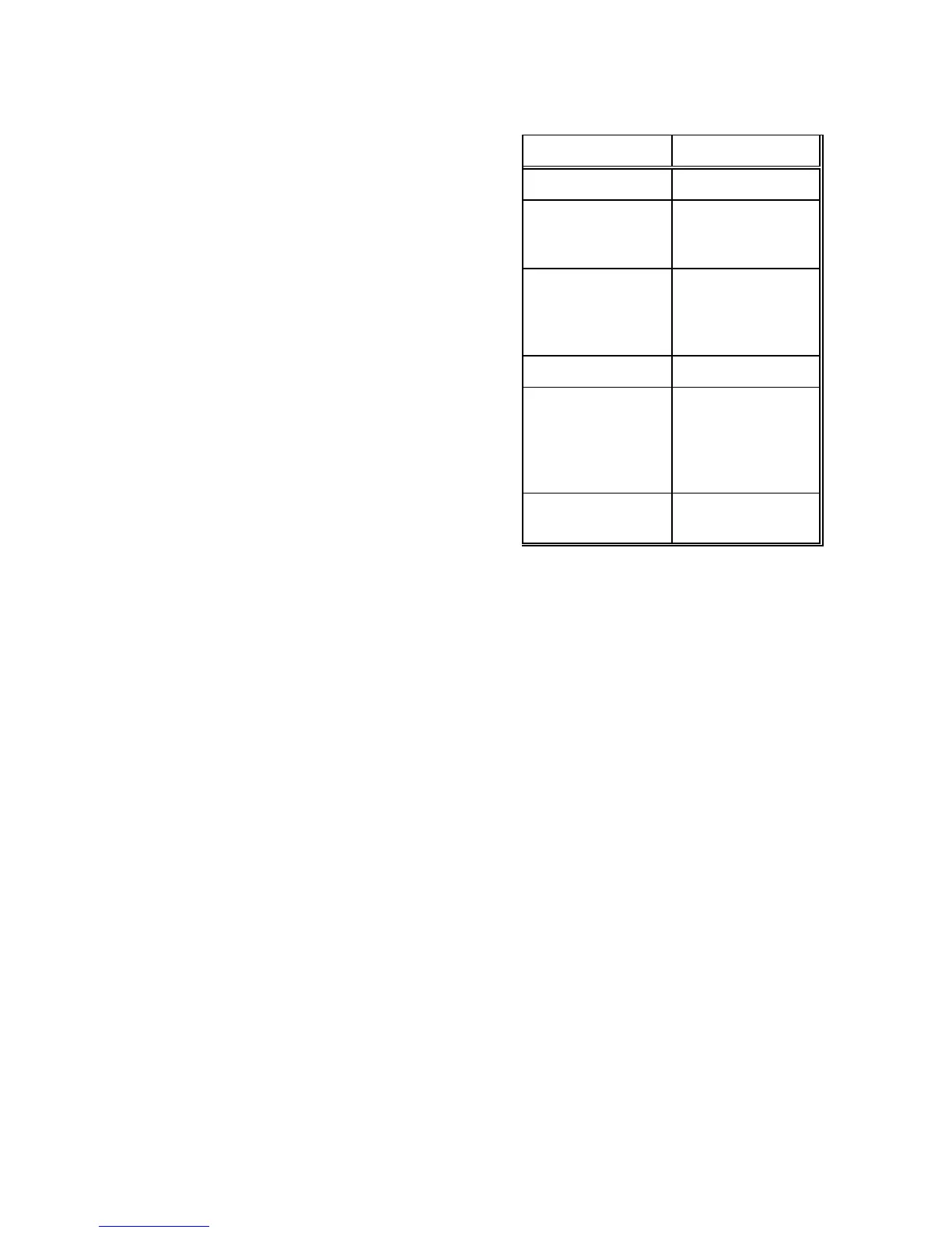
Table II - RECOMMENDED CABLES
USE TYPE
Pilot Power 2 X 16 GAUGE
-Steering Drive-
12/24/32VDC
Solenoid Valve
3 X 18 GAUGE
-Steering Drive-
CT2,CT3,CT4,
CT5 and CT6
Drive Box
Refer to the
Instructions
Supplied with
Drive Box
Rudder Follower 3 X 18 GAUGE
Navigation
Interface
2 X 24 GAUGE
with OVERALL
SHIELD. Shield
terminated at the
Nav Device ONLY
Rudder Angle
Indicator
2 X 24 GAUGE