22
With either rudder follower.
The distance between the centerline of
the rudder post and the rudder follower
must not exceed 24 inches. Make sure
that the ball joints on the rudder arm and
rudder follower arm are facing upwards
as shown in Figure 4. Snap the rod
assembly onto the ball joints. Be sure to
close the release clamps on each socket.
Refer to Figure 5 or Figure 6 and adjust
the length of the rod to get the correct
geometry with the rudder dead ahead.
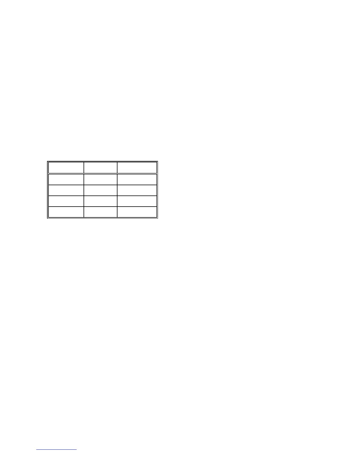
Table III - Rudder Follower Cable
Connections
Colour Terminal Description
White 14 +5V
Green 15 POS'N
Black 16 COM
Shield 2 GND
If the locking screw in the rudder follower
arm has been loosened, or the arm
removed from the rudder follower, re-
attach the arm and check the
potentiometer centring. When the rudder
is dead ahead, the electrical resistance
between the Black and Green wires and
the White and Green wires should be
equal (approx. 600 ohms each).
Be careful to check the installation for any
mechanical obstructions or binding of the
linkage, and correct it now, before it
becomes a problem.
The rudder follower is supplied with 50
feet of cable. Run the cable from the
rudder follower towards the distribution
box, ensuring that it is protected by hose
or conduit wherever it passes through fish
or cargo holds, or any other area where it
could be damaged.
If the length of cable supplied is too short
to reach all the way to the distribution box,
obtain a terminal strip and sufficient
additional cable from your dealer. Mount
the terminal strip in a convenient DRY
location. Connect the rudder follower
cable to the terminal strip and then the
additional length of cable. Strip the wires,
and attach them to the terminals in the
distribution box as shown Table III