1101/1201 Technical Manual
07/19/02 Page 14 1201 - JULY 19 '02
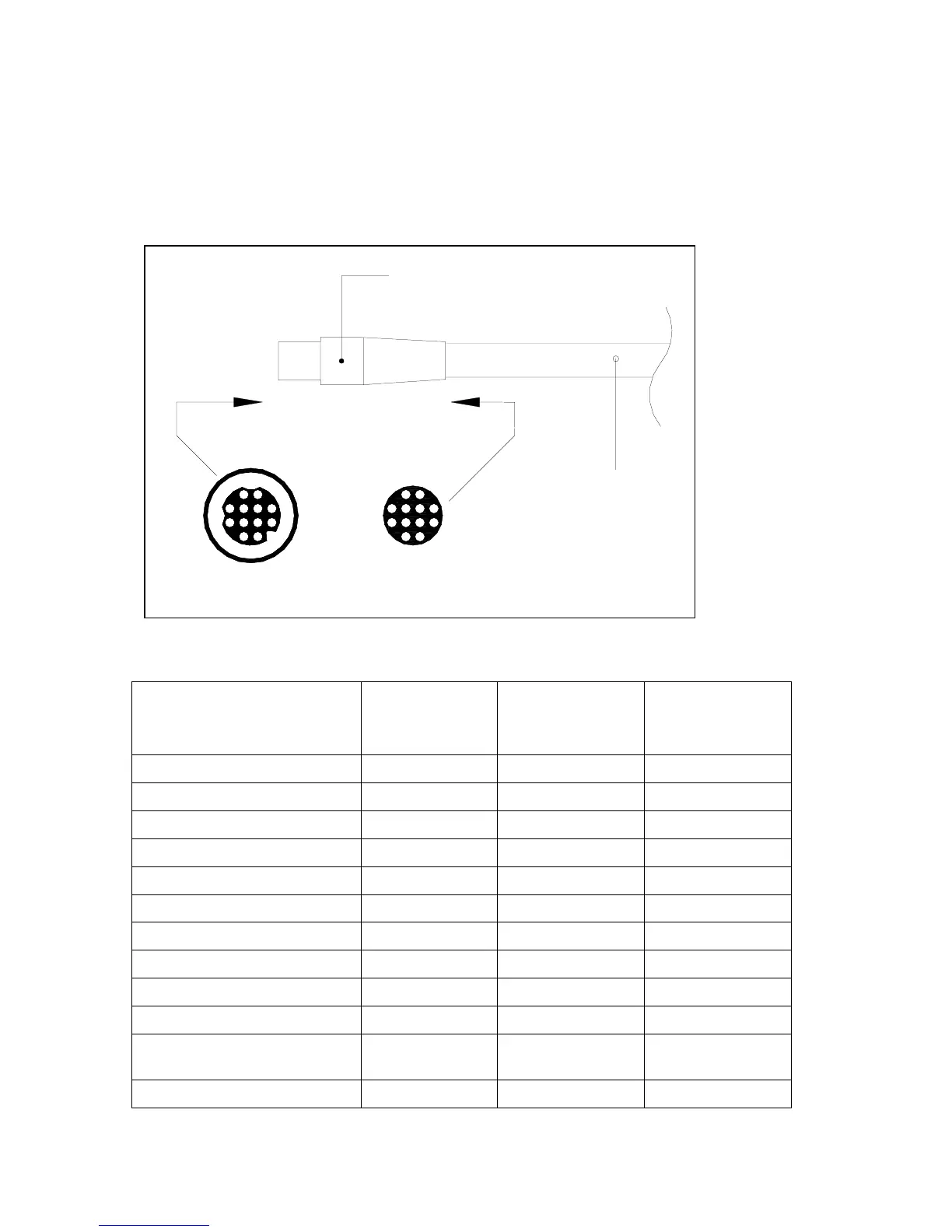
4.3 Head to SPU
Figure 4 Head Connector
WIRE COLOUR VIKING
CONNECTOR
PIN #
SIGNALS
HEAD
SIGNALS
AUXILARY
STATION
BLUE 1 ON/OFF CMND/CTRL
BROWN 2 +5Volts +5 Volts
PINK 3 Display Clock Display Clock
RED with BLUE stripe 4 Head Mode
VIOLET 5 Remote Data Rotary Switch “0”
BLACK 6 Key clock Data Turn/Adj
YELLOW 7 Serial Data IN Dodge/Alarm
RED 8 Port Drive Light Port/up
GREEN 9 STBD Drive Light STBD/Down
WHITE 10 Display Data Display Data
GREY with PINK stripe &
SHEILD DRAIN
11 Ground Ground
GREY 12 Alarm Rotary Switch “1”
1
7
6
5
1211
10
9
8
2
34
6
5
11
12
10
3
4
9
2
87
1
View along Arrow
Direction
26ft (8 meters)
12 +1 conductor cable
ComNav P.N. 83018
Plug with Backshell
12 Pin Black
Com Nav P.N. 40844
12 Fem ale Pins,
Com Nav P.N. 40214