1101/1201 Technical Manual
07/19/02 Page 15 1201 - JULY 19 '02
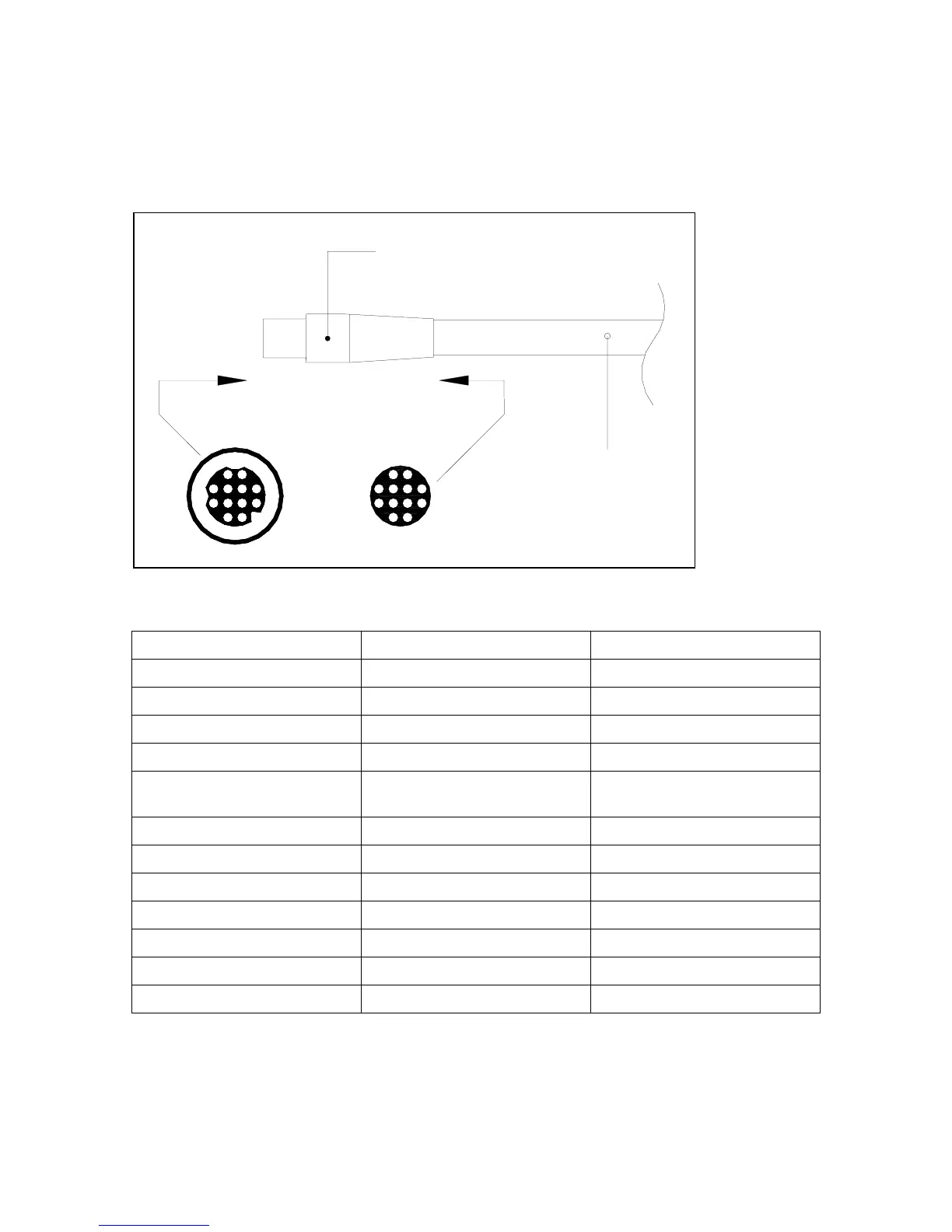
4.4 Distribution Box to SPU
Figure 5 Distribution Box Connector
WIRE COLOUR VIKING CONNECTOR PIN # SIGNAL
GREY with PINK stripe 1 Motor Monitor
VIOLET 2 Nav Signal
RED 3 Rudder Position
BLUE 4 Speed Control
SHIELD 5 Shield (Common to
Battery negative)
YELLOW 6 Battery (+)
GREY 7 Switched Power
PINK 8 Port Out
WHITE 9 STBD Out
BLACK 10 Rudder Power
BROWN 11 Battery (-)
GREEN 12 Rudder Common
1
7
6
5
1211
10
9
8
2
34
6
5
11
12
10
3
4
92
87
1
View along Arrow
Direction
10ft (3 meters)
11 +1 conductor cable
Com Nav P.N. 81747
Plug with Backshell
12 Pin Black
Com Nav P.N. 40844
12 Fem ale Pins,
Com Nav P.N. 40214