INS_FDW1000_EXP101 01/06/2020 PAGE 5
INSTALLATION AND OPERATION MANUAL FDW1000 / EXP101
TECH SUPPORT: 1.888.678.9427 / +44 (0)203 630 1653
Preparation
Tools
• #1 tip Phillips head screwdriver to remove metal covers
• small flat blade screwdriver to set the DIP switches
Before beginning
• determine the communications format for each reader;
» Wiegand with data words that are at least 8 bits (most readers), or;
» Wiegand with data words that are less than 8 bits (typical of reader / keypad combination
units), or;
» unsupervised F/2F (Casi Rusco systems)
• determine the number of expansion module pairs – if any – that will be needed (this quantity
will be one less than the number of readers in the link);
• determine whether Relay 3 will be reserved to monitor the status of the optical link;
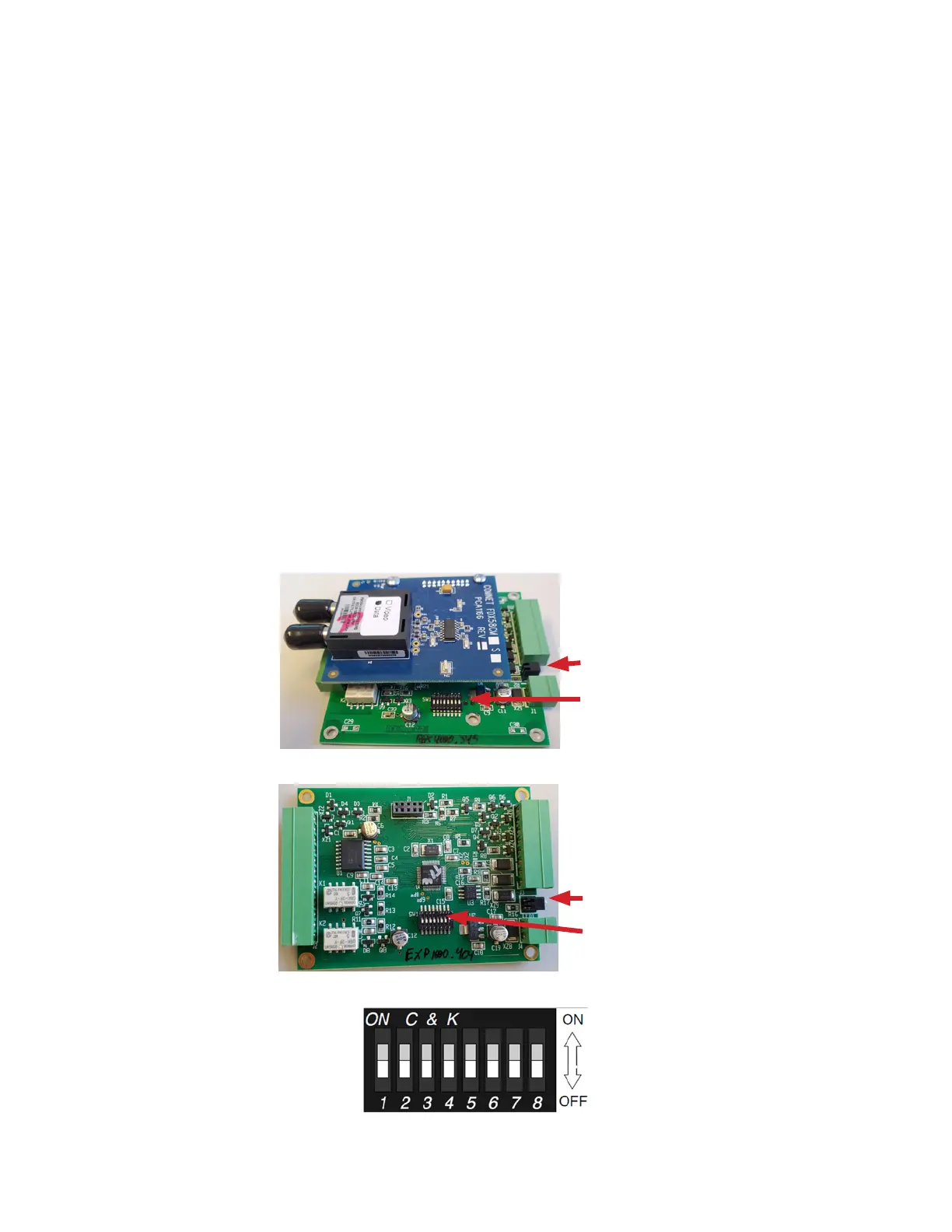
• locate the STATUS indicator LED (between the 2-pin power connector and the 8-pin terminal
strip – see Figures 1 and 2 below)
• with the cover removed, locate the eight DIP switches (OFF is toward the edge of the circuit
board and Switch 8 is closest to the power connector – see Figures 1, 2, and 3 below).
“STATUS” LED
DIP switches
Figure 1 – FDW1000
“STATUS” LED
DIP switches
Figure 2 – EXP101
Figure 3 – expanded view of DIP switches
Revision designation written
on the circuit board