INS_FDW1000_EXP101 01/06/2020 PAGE 9
INSTALLATION AND OPERATION MANUAL FDW1000 / EXP101
TECH SUPPORT: 1.888.678.9427 / +44 (0)203 630 1653
Configuring an EXP101 – current version – (rev .4xx range)
• Do not apply power to the EXP101. Remove all copper and signal connections. Remove the
metal housing to expose the DIP switches.
• Turn all DIP switches OFF.
• DIP Switch 1 on the EXP101 is used during factory testing but is not used during configuration
and should remain OFF.
• Using DIP Switch 2, set each unit as an EXP101/C (Central unit) or as an EXP101/R (Remote unit).
• Turn DIP Switch 2 ON to make the unit an EXP101/C (Central unit).
• Leave DIP Switch 2 OFF to make the unit an EXP101/R (Remote unit).
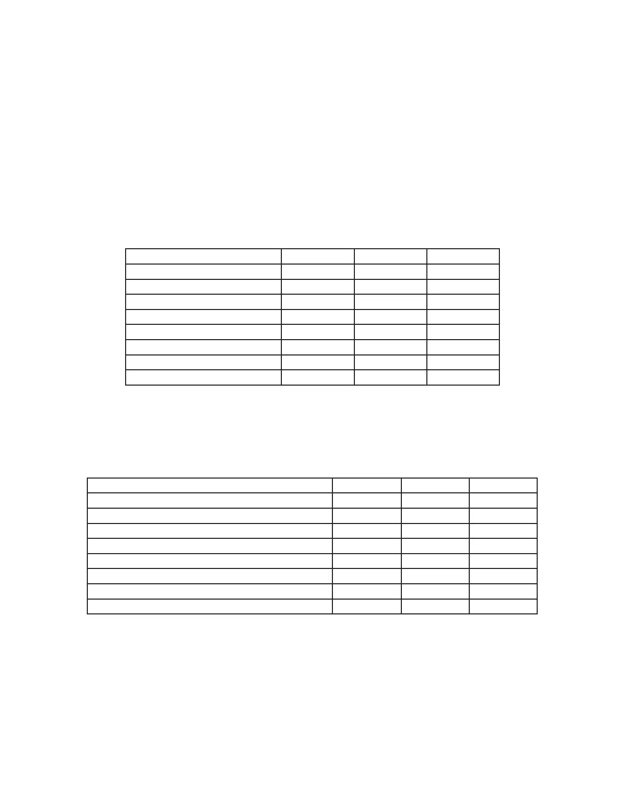
• Using DIP Switches 3, 4, and 5, set the communications format using the following table:
Communications Format DIP Switch 3 DIP Switch 4 DIP Switch 5
Not used OFF OFF OFF
Wiegand OFF OFF ON
Wiegand, no filter OFF ON OFF
strobed rising edge (MR-5) OFF ON ON
strobed rising edge (Dorado 644) ON OFF OFF
strobed rising edge (Mag-Tek) ON OFF ON
strobed falling edge ON ON OFF
unsupervised F/2F ON ON ON
• Using DIP Switches 6, 7, and 8, set the polling address of each pair of EXP101s using the table
below.
• If only one pair of EXP101s will be used, set the EXP101/C and the EXP101/R to polling address 1.
• If more than one pair of EXP101s will be used, set one pair of EXP101/C and EXP101/R to polling
address 1. Address the next pair using polling address 2 and continue sequentially as needed.
Number of EXP101 Pairs DIP Switch 6 DIP Switch 7 DIP Switch 8
Not used OFF OFF OFF
one pair of EXP101s – polling address 1 OFF OFF ON
two pairs of EXP101s – polling address 2 OFF ON OFF
three pairs of EXP101s – polling address 3 OFF ON ON
four pairs of EXP101s – polling address 4 ON OFF OFF
five pairs of EXP101s – polling address 5 ON OFF ON
six pairs of EXP101s – polling address 6 ON ON OFF
seven pairs of EXP101s – polling address 7 ON ON ON
• Apply power to the EXP101. The unit is now ready to use.
A common ground connection is critical for proper operation. At each remote location, a common
ground must exist between the reader(s), the FDW1000/R, and any EXP101/Rs. At the central loca-
tion, a common ground must exist between the panel, the FDW1000/C, and any EXP101/Cs.