INS_FDW1000_EXP101 01/06/2020 PAGE 25
INSTALLATION AND OPERATION MANUAL FDW1000 / EXP101
TECH SUPPORT: 1.888.678.9427 / +44 (0)203 630 1653
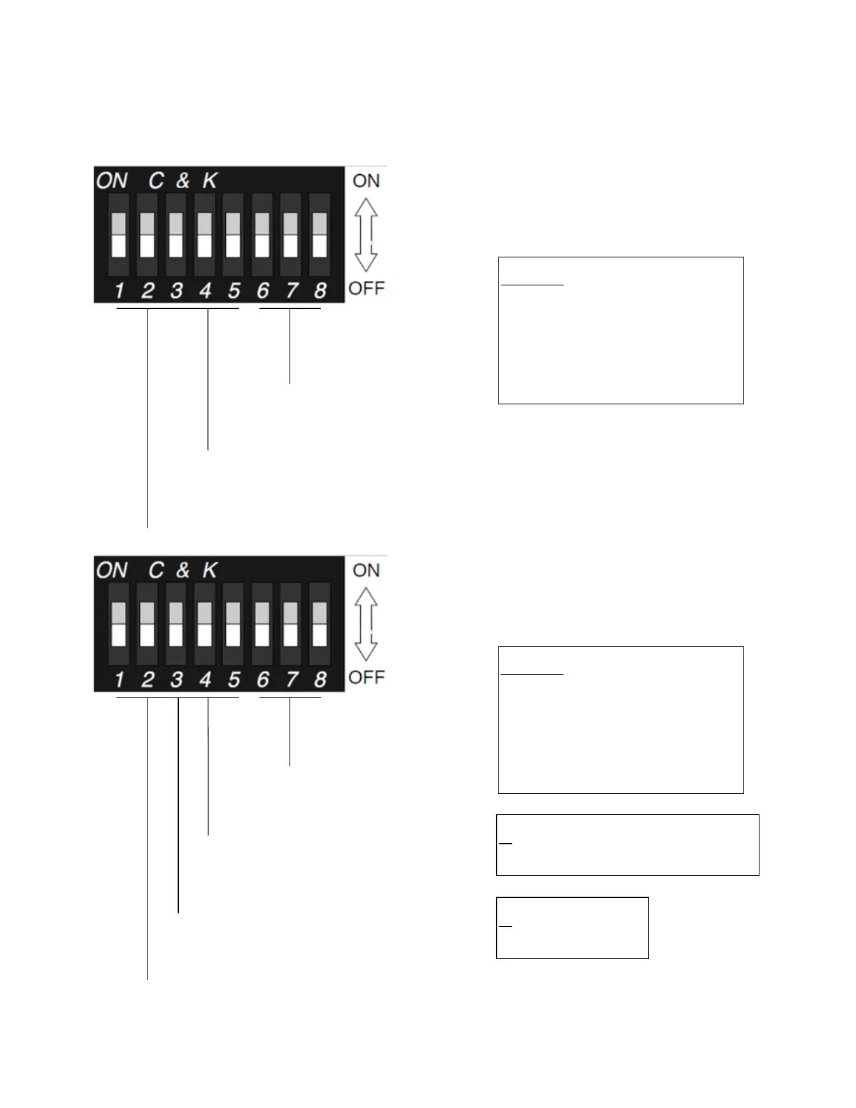
DIP switch maps
Current FDW1000s (.3xx Revision Designations) and Current EXP101s (.4xx Revision
Designations) Only
DIP Switches 1 and 4
put the FDW into
initialization mode.
DIP Switches 6,
7, and 8 set the
data interface.
DIP Switches 2,
3,
and 5 are not used
during initialization
.
Data Interface Select
6
7 8
0 0 0 not used
0 0 1 Wiegand
0 1 0 Wiegand No Filter
0
1 1 Strobed Rising (MR5)
1 0 0 Strobed Rising (Dorado 644)
1 0 1 Strobed Rising (
Mag
-Tek)
1 1 0 Strobed Falling
1 1 1 Unsupervised F
/2F
FDW
Initialization
DIP switches 1, 2,
and 5 are not used
in programming mode.
DIP Switches 6, 7, and
8 set the number of
expansion module pairs.
DIP Switch 3 sets the
FDW to Central or
Remote mode.
FDW
Programming
DIP Switch 4
sets the Relay
Channel 3
function.
Central / Remote Select
3
ON Central
OFF Remote
Relay Channel 3 Function Select
4
ON Monitors the status of the optical link
OFF Independent contact closure channel
Number of Pairs of Expansion Modules
6 7 8
0 0 0 not used
0 0 1 1 pair
0
1 0 2 pairs
0 1 1 3 pairs
1 0 0 4 pairs
1 0 1 5 pairs
1
1 0 6 pairs
1 1 1 7 pairs