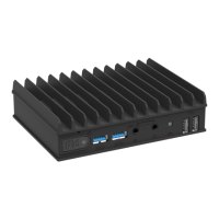
The Compulab fitlet3 is a miniature, fanless industrial PC designed for robust, versatile, and user-friendly operation, suitable for use as an IoT gateway. Its fanless design eliminates the need for maintenance after installation.
Function Description
The fitlet3 serves as a compact and durable computing platform, ideal for industrial applications and IoT gateway functions. It is designed to operate reliably in a wide range of temperatures and environments, offering extensive connectivity and expansion options. The device supports various operating systems, including Windows 10, Windows 11, and Linux. Its modular design allows for customization through Function And Connectivity Extension T-Cards (FACET Cards) and other optional accessories, enhancing its adaptability to specific application requirements.
Important Technical Specifications
CPU:
- Intel® Atom x6425E: 4 Core, Base: 2.0 GHz, Boost: 3.0 GHz, TDP: 12 W
- Intel® Celeron J6412: 4 Core, Base: 2.0 GHz, Boost: 2.6 GHz, TDP: 10 W
- Intel® Atom x6211E: 2 Core, Base: 1.3 GHz, Boost: 3.0 GHz, TDP: 6 W
Memory:
- Type: SO-DIMM DDR4 up to 3200MT/s
- Max. capacity: 32 GB
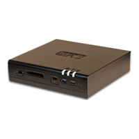
Storage:
- M.2 Key-M: PCIe x4 / SATA for M.2 NVMe or SATA, size up to 2280
- M.2 Key-B: SATA for M.2 SATA, size up to 2260
- 2.5" HDD/SSD: Optional M.2 to SATA expansion for 2.5" HDD / SSD
Display:
- HDMI: HDMI 1.4b (up to 3840 x 2160 @ 30Hz)
- Mini-Display Port: DP 1.2 (up to 4096 x 2160 @ 60Hz) Dual mode
Ethernet:
- Controllers: 2x Gigabit Ethernet on RJ45 (2x Internal MAC with discreet PHY)
- Speed: 1000 Mbps / 100 Mbps / 10 Mbps
- Optional FC3-LAN: Additional 2x GbE LAN on RJ45
- Optional FC3-OPLN: Additional 1x GbE LAN on SFP+ for optical LAN
- Optional FC3-POED: Additional 1x GbE LAN on RJ45 with PoE device capabilities
Wireless Connectivity:
- On-board: Optional On-board module with Wi-Fi 6E, BT 5.2
- M.2 Key-E: For M.2 2230 module with Wi-Fi 6E, BT 5.2
- M.2 Key-B: For M.2, LTE/5G modem, with micro-SIM tray
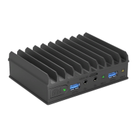
USB:
- USB 2.0: 4x USB 2.0 on USB Type-A
- USB 3.1: 2x USB 3.1 on USB Type-A
Serial/GPIO:
- Type: Isolated serial and GPIO, up to 24V, on terminal block
- Serial port: Optional isolated RS-232/422/485
- GPIO: 2x isolated GPI + 2x isolated GPO
Audio:
- Codec: Optional audio codec
- Interfaces: Optional analog output, analog input on 3.5 mm jacks
Power:
- Input power: 7V – 42V, up to 5A DC input
- Connector: 5.5 mm power jack w/ locking
- Power supply unit: Including universal AC wall mount power supply
- Optional FC3-PoE: Input power by PoE, GbE LAN on RJ45
TPM:
- Internal FTPM: Intel® PTT
- Discreet TPM: Optional discreet TPM 2.0
OS Support:
- Windows 10 Pro / Windows 10 LTSC 2021 IoT Enterprise
- Windows 11 Pro
- Linux Mint / Ubuntu
Operating Environment:
- Commercial temperature: 0°C to 45°C
- Extended temperature: -20°C to 70°C
- Industrial temperature: -40°C to 85°C
- Humidity: 5% - 95% non-condensing
Physical Characteristics:
- Cooling: Fanless, passive cooling
- Dimensions: 132.8 mm × 100 mm X 34.8 mm
- Weight: ~420 gr.
- Mounting: Side / bottom VESA / DIN Rail mount
Expansion Boards:
- FC3-LAN: 2x GbE LAN on RJ45 (M.2 Key-E (FACET))
- FC3-POED: GbE LAN PoE device on RJ45 (M.2 Key-E (FACET))
- FC3-OPLN: GbE on SFP+ for optic LAN (M.2 Key-E (FACET))
- EB-M2SATA: SATA expansion for 2.5” HDD / SSD (M.2 Key-M or M.2 Key-B)
Optional Accessories:
- FITLET3-ACC-PSU: Universal power supply unit
- FITLET3-ACC-BRKT: VESA mounting bracket
- FITLET3-ACC-DIN: DIN rail mounting kit (Requires VESA mounting bracket)
- FITLET3-ACC-DINSD: Side DIN rail mounting kit (does not require VESA mounting bracket)
- FITLET3-ACC-POWBTN: Remote power button with LED with 25cm wire
Usage Features
Quick Start Guide:
To use the fitlet3, RAM and a storage device are required (if not pre-installed). A display with HDMI or DisplayPort input, an HDMI or mini-DisplayPort cable, and a USB keyboard and mouse are also necessary. The specific configuration of the fitlet3 is detailed on a label attached to the bottom side of the computer. If RAM and storage are not installed, the fitlet3 will not boot.
Opening the Device:
To install RAM, storage, and the RTC battery, the fitlet3 needs to be opened. This requires a Phillips screwdriver.
- Place the fitlet3 bottom-up on a flat surface.
- Unscrew the four screws counter-clockwise.
- Lift the bottom cover to remove it; side panels should fall off.
- Lift the fitlet3 from the top cover.
Installing RAM:
The RAM socket is on the top side of the motherboard. The fitlet3 accepts a single SODIMM DDR4 module. Insert the DDR4 SODIMM module and press it down until it latches firmly on both sides.
Installing M.2 Cooling Plate, SSD, and Modem:
The M.2 cooling plate serves multiple purposes: allowing installation of various M.2 devices, providing cooling, assisting in battery placement, and managing cables.
- M.2 Key-M supports SATA of NVME modules (2230, 2242, 2260, or 2280).
- M.2 Key-B supports SATA M.2 modules or modems (30mm, 42mm, 52mm, or 60mm lengths; 22mm or 30mm widths).
The SSD must be fastened to the M.2 cooling plate, which is then placed on the underside of the motherboard and fastened to the front and back panel.
- Peel off the protective film from the two thermal pads.
- Place the red M.2 spacer according to the length of the M.2 SSD, ensuring the recessed side faces the alignment screws. Insert the M.2 fastening screw but do not tighten yet.
- Place the edge of the M.2 SSD against the fastening screw. Press the SSD firmly against the thermal pad until its connector edge is seated between the alignment pins. The connector edge should protrude above the M.2 cooling plate.
- Tighten the fastening screw.
- Turn over the M.2 cooling plate and push the M.2 SSD into its socket at the underside of the motherboard.
- Push down the M.2 cooling plate and tighten the 3 panel screws.
Installing Optional WiFi/BT Module:
By default, the WiFi/BT module is not installed.
- Assemble the adapter.
- Tighten the appropriate screws.
- Insert the red spacer and fastening screw, but do not tighten it.
- Insert the WiFi/BT module into the appropriate socket at an angle.
- Press it down until it latches the spacer.
- Tighten the fastening screw.
Installing RTC Battery:
The RTC battery maintains time and date when the fitlet3 is disconnected from power. It is typically shipped unplugged to prevent discharge during warehousing.
- Connect the battery plug to the corresponding socket.
- Route the wire through the slots of the M.2 cooling plate to minimize clutter.
- Place the battery in the marked pocket; it will be secured once the bottom cover is assembled.
Re-assembling the Device:
- Place the fitlet3 onto the top cover (it is symmetric, so direction does not matter).
- Place the bottom cover onto the fitlet3. Ensure the tall U-shaped boss is near the M.2 sockets; otherwise, the bottom cover will not fit.
- Click both side panels into place.
- Tighten the 4 screws.
Connecting the Device:
- Ensure RAM and storage are installed.
- Connect the display using an HDMI or mini-DP cable.
- Connect a USB keyboard and mouse.
- Insert the DC plug into the fitlet3 DC-in jack.
- Rotate the DC plug clockwise 90° to secure.
- Attach the correct AC blade to the power supply and plug it into an AC outlet. The power button LED should turn green, and an image should appear on the display shortly.
- Connect an Ethernet cable as needed; the link LED on RJ45 should light up.
- If a WiFi adapter is installed, connect the included antennas by screwing them clockwise onto the SMA connectors on the side panel.
Entering BIOS Setup:
- Turn off the fitlet3.
- Turn it on while holding down the Del key to access the AMI Inc. BIOS utility.
Installing and Booting Operating System:
Refer to the official website for detailed instructions on installing and booting an operating system.
Maintenance Features
Safety Instructions:
- Disconnect all power sources before opening the computer cover or panels.
- Only certified service technicians should perform repairs.
- Avoid electrostatic discharge by handling components and cards with care.
- When disconnecting a cable, pull on its connector or pull-tab, not on the cable itself.
RTC Battery:
The RTC battery keeps the time and date when the fitlet3 is unpowered. It can hold a charge for approximately 5 years when disconnected and significantly longer when connected to power. Users can purchase and replace the battery.
Warranty:
Compulab guarantees products against defects in workmanship and material for 60 months from the shipment date. The sole remedy is repair or replacement of the defective product at no charge. The warranty is void if the product has been altered or damaged by accident, misuse, or abuse.
RMA (Return Merchandise Authorization):
- Keep the original package for shipping.
- Contact the seller of the fitlet3.
- When issuing an RMA, provide the fitlet3 serial number, buyer's name and address, invoice number, and problem description.
- If purchased directly from Compulab, email
rma@fit-pc.com.
WEEE Statement:
The device and its Li-Mn battery must be disposed of separately from general household waste at the end of their useful life, in accordance with local waste collection regulations.