IP CAMERA QUICK START GUIDE
1. CONTENTS
Packaging Contents
IP Camera x1 Wall Plugs x3
Fitting Screws x3 Torx Wrench x1
RJ45 Waterproong Cap x1 Conduit Key x1
Analogue SVO Cable x1 Mounting Template x1
2. INSTALLATION
Remove the Dome Cover
Loosen the three tamper screws using the provided torx
wrench. Lift the dome cover. If you plan to use a conduit xing,
remove the conduit cap using the included conduit key.
Surface Mount – Method 1
Use the included mounting template (option 2) to mark and
pre-drill the required holes. Remove two of the three base
locking screws. Use two of the 2.8” screws to mount the
camera directly to the mounting surface. Then remove the
third base locking screw and install the nal 3.8” screw. Position
the lens module in the desired conguration, then replace the
dome cover.
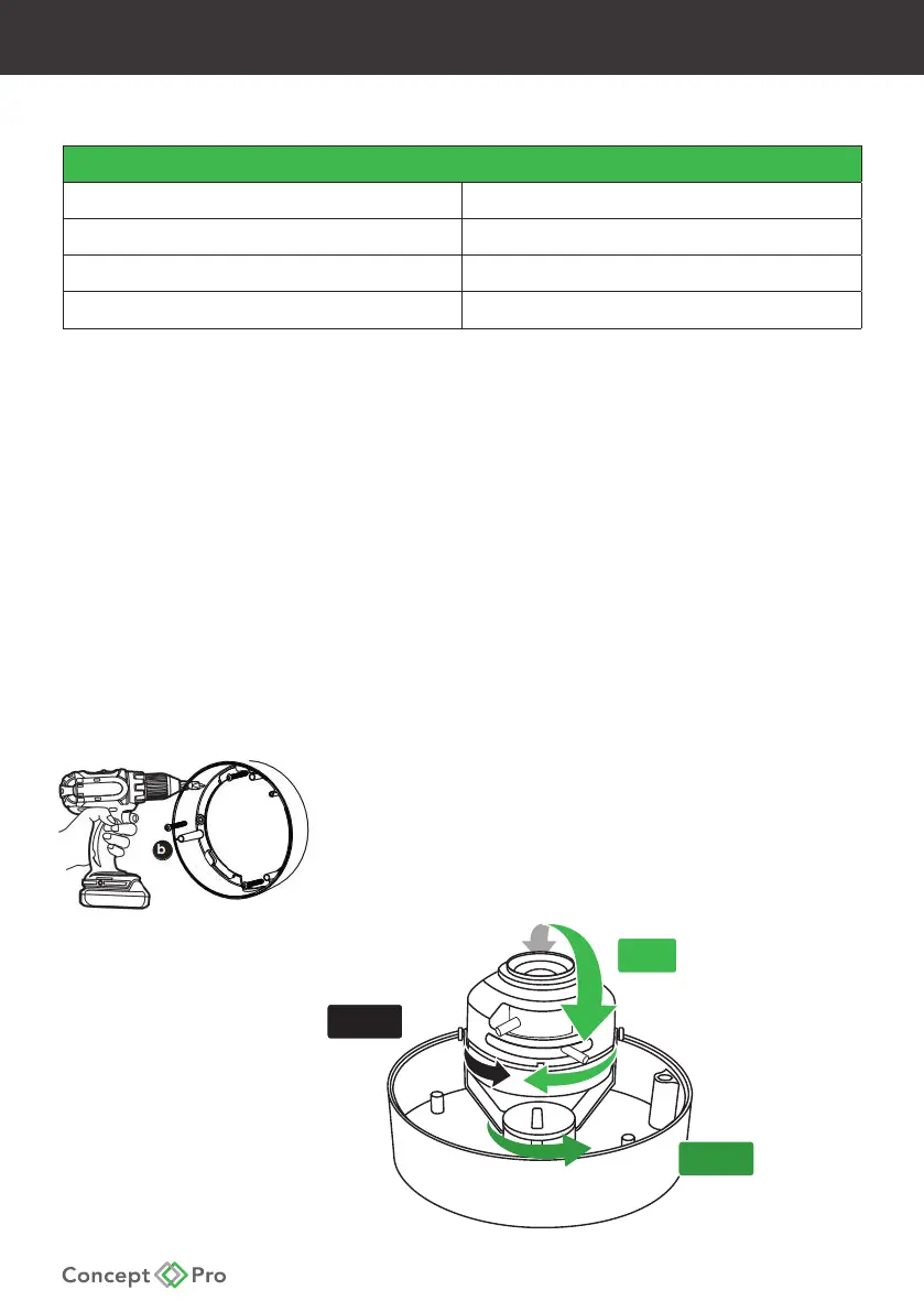
Surface Mount – Method 2
Use the included mounting template (option 1) to mark
and pre-drill the required holes. Remove the camera base
by unscrewing the three base locking screws, and turn the
camera module approximately 5° counter-clockwise to
detach the camera base from the camera module. Install the
base as indicated using the included 1.2” xing screws.
360º
90º
360º