IP CAMERA QUICK START GUIDE
3. CONFIGURING THE CAMERA
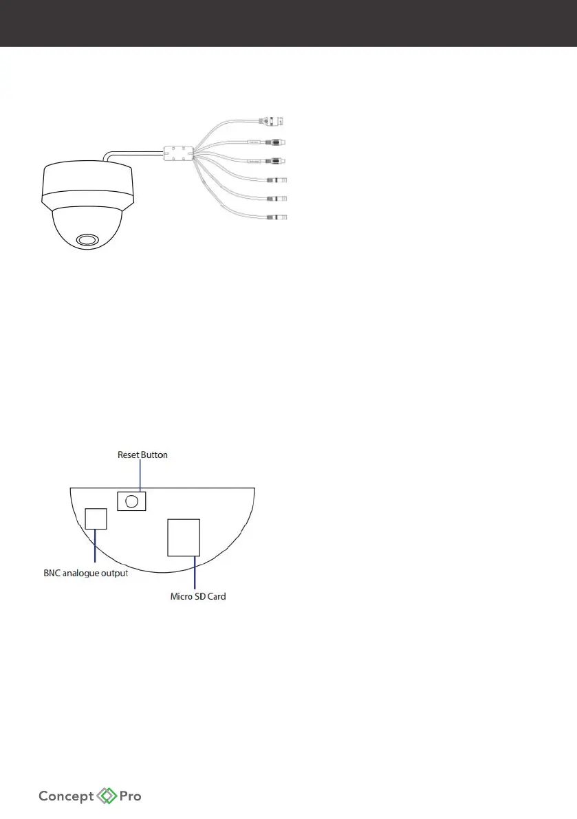
Outer Camera Connections
RJ45 10M/100M Base-T Ethernet (PoE/Video)
Audio Input
Audio Output
DC1V Power Connector
Alarm Input
Alarm Output
- If using DC12V to power the camera, ensure the power supply matches the camera power
supply requirements specied and connect to the camera DC12V power input.
- Connect the RJ45 connector to a network switch. If the network switch supports Power over
Ethernet (PoE), disconnect any DC12V power connections.
- View the image on a monitoring device—such as a BNC test monitor—to conrm the
power and video connections are properly working.
Inner Camera Connections
Reset Button
Analogue Service Video Output*
Micro SD Card Slot
* The Analogue SVO is for installation purposes only.