CONCEPT2.COM
Page 7
012611
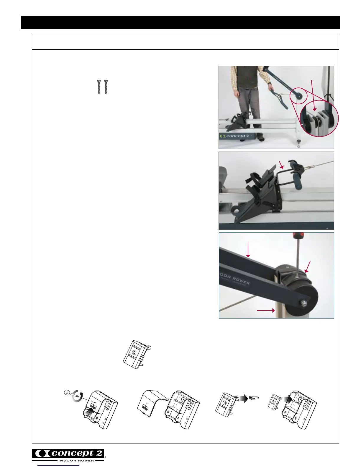
photo V
Assembly continued
photo U
photo W
CONCEPT2 DYNAMIC INDOOR ROWER
Top Pulley
Foot Carriage Handle Hook
Front Leg
End Cap
Monitor Arm
Front Leg
Step 10: Install Handle Drive Cord and Front Leg
End Cap
(2) 1 3/8” (3.49 cm)
PN 2228
Run the handle with drive cord around the top pulley.
See photo U.
Pull the handle toward the foot carriage until it can be
placed in the foot carriage handle hook. See photo V.
Insert the front leg end cap over open end of front leg,
where monitor arm joins the leg. Insert screws all the
way until the screw head meets the end cap. Even
though the screws will continue to spin, they are as
tight as they need to be. See photo W.
Step 11: FOR PM4 ONLY - Install Rechargeable
Battery Pack in the Performance Monitor (PM4)
(1) Rechargeable Battery Pack