• For TelePACE applications use the AIN Controller RAM Battery V register assignment to read
the lithium battery voltage.
• For ISaGRAF applications use the ainbatt I/O connection to read the lithium battery voltage.
3.4 Digital /Counter Inputs
The SCADAPack 32P has three Digital / Counter inputs. These inputs are labeled DIN\Counter 0, 1
and 2 on the P4 terminal connector. These inputs operate as AC or DC digital inputs or as counter
inputs.
• For DC inputs the maximum input voltage is 30V and the minimum voltage to turn the input ON
is 10V.
• For AC inputs the maximum input voltage is 24Vrms and the minimum voltage to turn the input
ON is 10Vrms.
• For counter inputs the maximum frequency is 5KHz with the filters off.
The DIN/Counter inputs can be used as both digital inputs and counter inputs in an application
program.
• For TelePACE applications use the CNTR Controller Counter Inputs register assignment to
read the DIN/Counter inputs as counters and the DIN Controller Digital Inputs register
assignment to read the DIN/Counter inputs as digital inputs
• For ISaGRAF applications use the cntrCtrl I/O connection to read the DIN/Counter inputs as
counters and the dinCtrl I/O connection to read the DIN/Counter inputs as digital inputs.
Each of the three digital / counter (DIN/Counters) inputs on the SCADAPack 32P controller has a
switch selectable filter, which limits the maximum input frequency. Filtering limits the maximum
digital input or counter frequency to approximately 30Hz. Refer to section 6.7.1-Digital Input
Filters for filter selection information.
• Use a filter for 50 or 60Hz digital inputs and for low speed counting applications that experience
problems due to contact bounce.
• Do not use filtering for high speed counting applications.
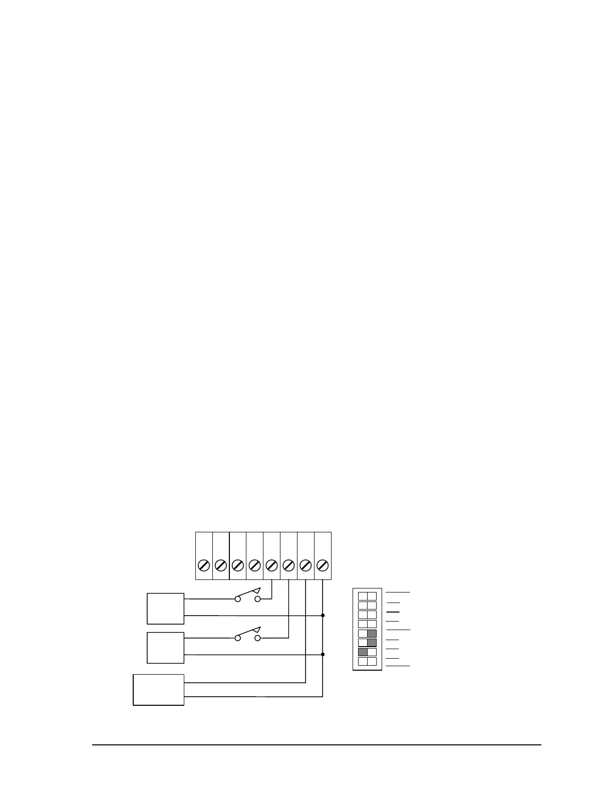
An example of wiring each type of input is shown in the diagram below.
Connection Example:
SW1 Filter 0 is ON to debounce contacts.
SW1 Filter 1 is ON to filter AC.
SW1 Filter 2 is OPEN for high speed counting.
34
0
+
24V
DIN/Counter
2
1
5
6
7
8
P4
COM21
16Vrms
+
Pulse Output
SW 1
2
1
2
3
4
0
1
not used
Options
Filters
SCADAPack 32P Controller Hardware Manual
May 26, 2006
12