4.3 RS-232 Cables
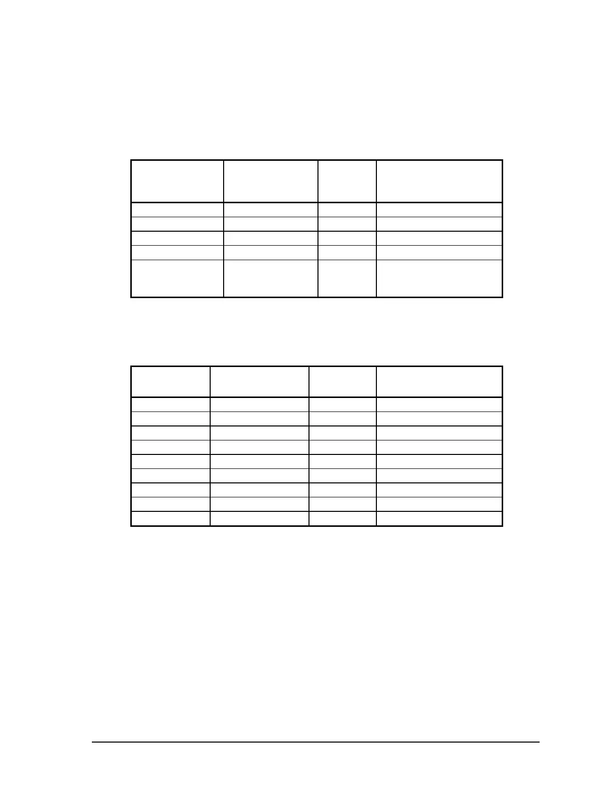
4.3.1 RJ-45 to DE-9S DTE
This cable is used to connect from an RJ-45 based RS-232 port on the SCADAPack 32P controller to
DE-9P connector on a DTE such as a PC. A 10 ft. long cable is available from Control Microsystems
as part number 297217.
RJ-45
8 Pins
SCADAPack 32P
DTE Function
DE9S
DTE
Function
DE9S
Shield connects to shell
6 TxD RxD 2
5 RxD TxD 3
4 GND GND 5
1, 2, 3, 7 and 8
are not connected
at this end.
GND GND No wires connected at
this end.
4.3.2 RJ-45 to DE-9P DCE
This cable is used to connect from an RJ-45 based RS-232 port on the SCADAPack 32P controller to
DE-9S connector on a DCE such as a modem. A 15 inch long cable is available from Control
Microsystems as part number 297218.
RJ45 SCADAPack 32P
DTE Function
DE-9P DCE
Function
DE-9P
Shield connects to shell
3 DTR DTR 4
6 TxD TxD 3
5 RxD RxD 2
2 DCD DCD 1
4 GND GND 5
7 CTS CTS 8
8 RTS RTS 7
1 +5V +5V 9
4.4 RS-485 Serial Communication Port
Serial port COM1 on the SCADAPack 32 controller may be configured as an RS-485 serial
communication port. A jumper must be installed on J9 to operate COM1 in RS-232 mode. Refer to
section 3.1-Field Wiring Connections for the location of J9.
When configured as a RS-485 port COM1 transmits and receives differential voltages to other RS-
485 devices on a network. The RS-485 specification allows a maximum of 32 devices connected on
a single RS-485 network. The recommended specification for RS-485 is the cable length should not
exceed a maximum of 4000 feet or 1200 meters. Termination resistors are required when using long
cable lengths and high baud rates. Refer to section 4.4.3-RS-485 Termination Resistors for
information on termination resistors.
The signal grounds of the RS-485 devices in the network are not connected together but instead are
referenced to their respective incoming electrical grounds. The grounds of the RS-485 devices on the
network must be within several volts of each other.
SCADAPack 32P Controller Hardware Manual
May 26, 2006
20