6.7 Configuration Switches
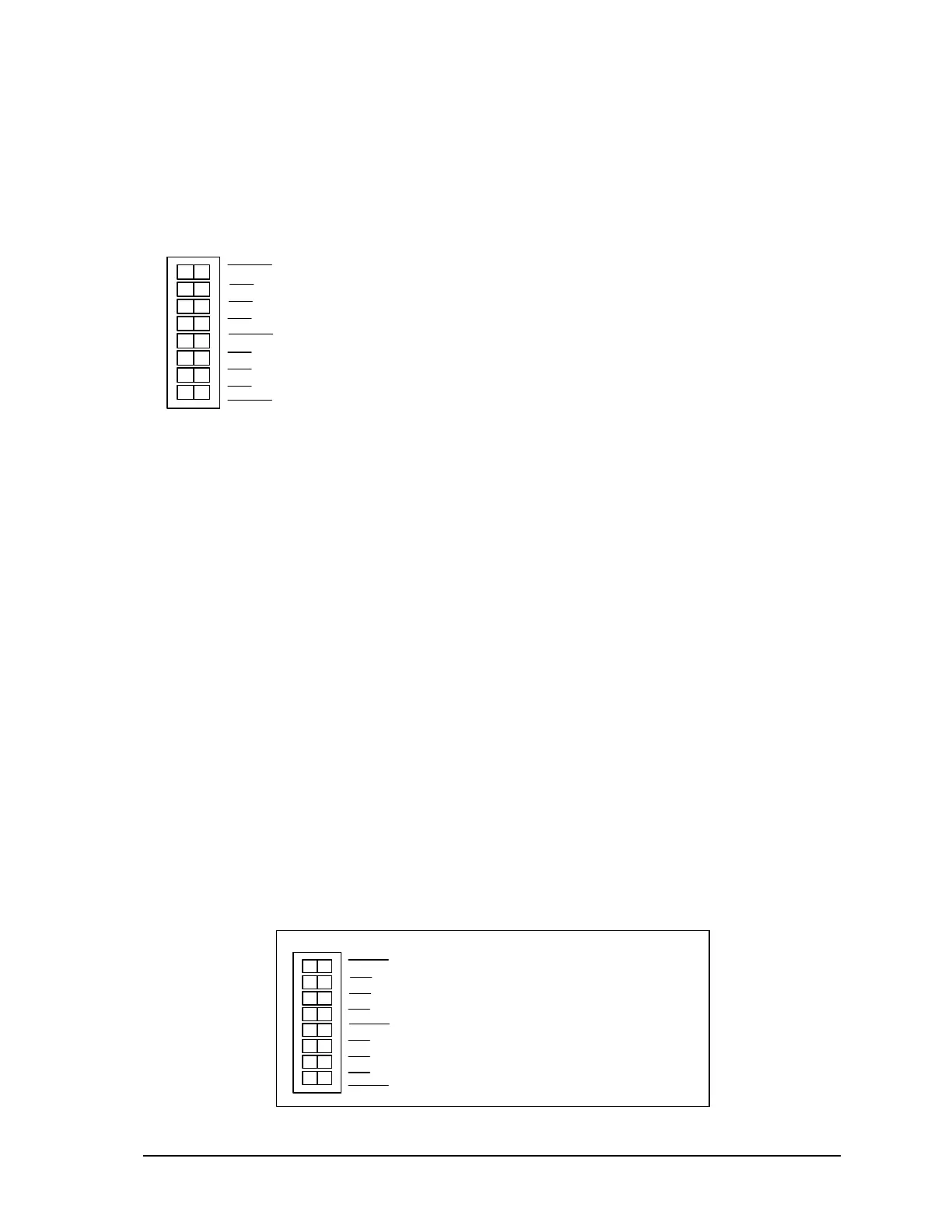
The SCADAPackl32 SCADAPack 32P SW1 is an eight position DIP switch. The first seven
switches on SW1 are used to configure digital / counter input filtering and analog input and output
ranges. SW1 is shown in the following diagram. Refer to 3.1.1-5232 Controller Board Field Wiring
Connectors for the location of SW1 on the SCADAPack 32P SCADAPack 32P.
SW 1
2
1
2
3
4
0
1
not used
Options
Filters
•
SW1-1 Option 1 Available for application programs.
•
SW1-2 Option 2 Available for application programs.
•
SW1-3 Option 3 Available for application programs.
•
SW1-4 Option 4 Available for application programs.
•
SW1-5 Filter 0 DIN/Counters input 0 filtering.
•
SW1-6 Filter 1 DIN/Counters input 1 filtering.
•
SW1-7 Filter 2 DIN/Counters input 2 filtering.
•
SW1-8 Not Used
C
Configuration switches can be changed with the power applied. Configuration changes take effect
immediately.
To select configuration switch functions:
• Remove the module cover and locate the configuration switches. See section 3.1-Field Wiring
Connections for SW1 location.
• Slide the switch actuator to the right side of the switch to enable the switch function.
• Slide the switch actuator to the left side of the switch to disable the switch function.
6.7.1 Digital Input Filters
Each of the three digital / counter (DIN/Counters) inputs on the SCADAPack 32P SCADAPack 32P
can be filtered. Filtering limits the maximum digital input or counter frequency to approximately
30Hz.
• Use a filter for 50 or 60Hz digital inputs and for low speed counting applications that experience
problems due to contact bounce.
• Do not use filtering for high speed counting applications.
SCADAPack 32P SCADAPack 32P SW1, switches Filter 0, Filter 1 and Filter 2 switches control the
input filter functions.
• Filter 0 for DIN/Counters input 0.
• Filter 1 for DIN/Counters input 1.
• Filter 2 for DIN/Counters input 2.
SW 1
2
1
2
3
4
0
1
not used
Options
Filters
•
To enable a filter, slide the Filter 0, Filter 1
or Filter 2 actuator to the right side of the
sw i tch (cl osed).
•
To disable a filter, slide the Filter 0, Filter 1
or Filter 2 actuator to the left side of the
switch (closed).
SCADAPack 32P Controller Hardware Manual
May 26, 2006
33