Safety
Information
Product
Information
Mechanical
Installation
Electrical
Installation
Keypad and
Display
Parameters
Quick Start
Commissioning
Diagnostics Options Parameter List
UL Listing
Information
Commander SK Size 2 to 6 Getting Started Guide 17
Issue Number: 2 www.controltechniques.com
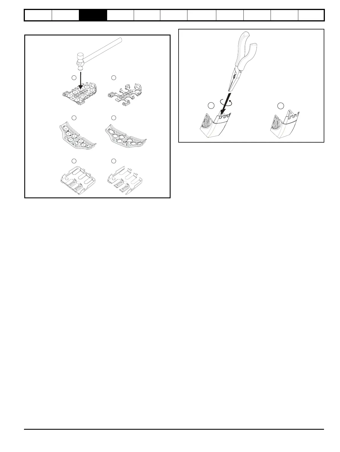
Figure 3-5 Removing the finger-guard and DC terminal cover
break-outs
Place finger-guard on a solid flat surface and hit relevant break-outs with
hammer as shown (1). Continue until all required break-outs are
removed (2). Remove any sharp edges once break-outs are removed.
Figure 3-6 Removing the terminal cover break-outs
Grasp the DC terminal cover break-outs with pliers as shown (1) and
twist to remove. Continue until all required break-outs are removed.
Remove any sharp edges once the break-outs are removed. Use the DC
terminal cover grommets supplied in the accessory box (Figure 2-2 on
page 14 and Figure 2-3 on page 14) to maintain the seal at the top of the
drive.
1
2
ll sizes
Size 3
only
1
2
1 2
Sizes 4 to 6
only
1
2