Safety
Information
Product
Information
Mechanical
Installation
Electrical
Installation
Keypad and
Display
Parameters
Quick Start
Commissioning
Diagnostics Options Parameter List
UL Listing
Information
Commander SK Size 2 to 6 Getting Started Guide 41
Issue Number: 2 www.controltechniques.com
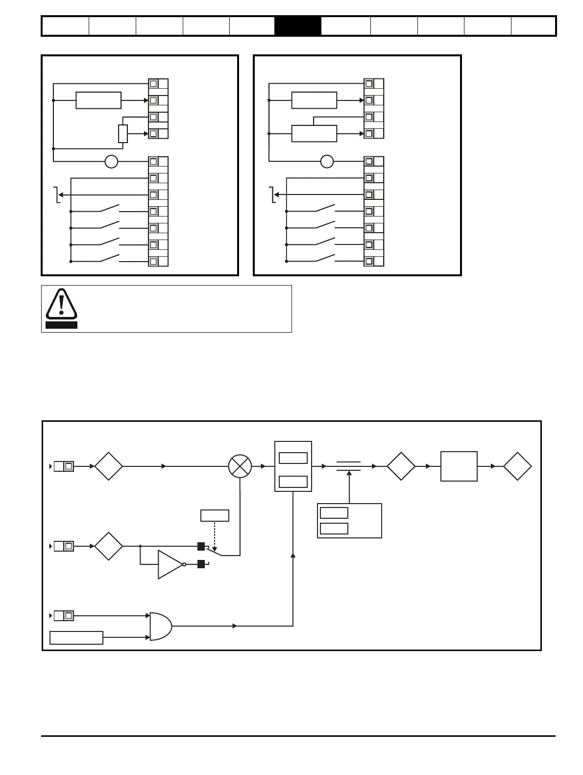
When Pr 05 is set to Pid, the following parameters are made available for adjustment:
•Pr 61: PID proportional gain
•Pr 62: PID integral gain
•Pr 63: PID feedback invert
•Pr 64: PID high limit (%)
•Pr 65: PID low limit (%)
•Pr 66: PID output (%)
Figure 6-9 PID logic diagram
Figure 6-7 Pr 05 = tor Figure 6-8 Pr 05 = Pid
When torque mode is selected and the drive is connected to
an unloaded motor, the motor speed may increase rapidly to
the maximum speed (Pr 02 +20%).
0V
Remote current speed
reference input (A1)
+10V reference output
Torque reference
input (A2)
+24V output
Drive Enable/Reset
(USA: /Stop)
Run Forward
(USA: Run)
Run Reverse
(USA: Jog)
Torque mode
l
t
Remote speed
reference input
V
_
+
10k
(2kmin)
+24V
0V
Eur
Analogue output
(motor speed)
Digital output
(zero speed)
T1
T2
T3
T4
B1
B2
B3
B4
B5
B6
B7
0V
+10V reference outpu
+24V output
Drive Enable/Reset
(USA: /Stop)
Run Forward
(USA: Run)
Run Reverse
(USA: Jog)
4-20mA PID
feedback input
V
_
+
+24V
0V
Eur
Analogue output
(motor speed)
Digital output
(zero speed)
PID feedback input
PID reference input
PID enable
0-10V PID
reference input
T1
T2
T3
T4
B1
B2
B3
B4
B5
B6
B7
WARNING
95
94
%
T4
T2
x(-1)
0
1
63
Invert
61
P Gain
62
I Gain
PID reference
input
%
PID feedback
input
B7
PID enable
&
Drive healthy
64
PID high
limit
65
PID low
limit
66
%
81
Drive
reference
Hz
%to
frequency
conversion
+
_