Safety
Information
Product
Information
Mechanical
Installation
Electrical
Installation
Keypad and
Display
Parameters
Quick Start
Commissioning
Diagnostics Options Parameter List
UL Listing
Information
Commander SK Size 2 to 6 Getting Started Guide 39
Issue Number: 2 www.controltechniques.com
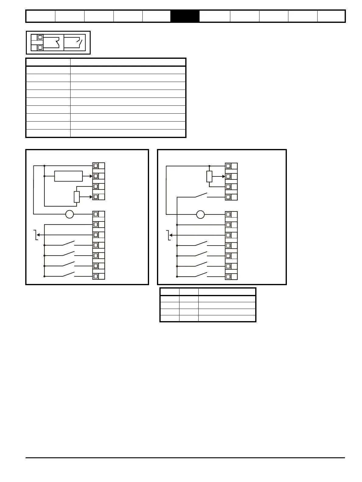
In all of the settings below, the status relay is set up as a drive healthy relay:
Configuration Description
AI.AV Voltage and current input
AV.Pr Voltage input and 3 preset speeds
AI.Pr Current input and 3 preset speeds
Pr 4 preset speeds
PAd Keypad control
E.Pot Electronic motorised potentiometer control
tor Torque control operation
Pid PID control
HUAC Fan and pump control
Figure 6-1 Pr 05 = AI.AV Figure 6-2 Pr 05 = AV.Pr
Terminal B7 open: Local voltage speed reference (A2)
selected
Terminal B7 closed: Remote current speed reference
(A1) selected
T5
T6
OK Fault
T1
T2
T3
T4
0V
Remote current speed
reference input (A1)
+10V reference output
Local voltage speed
reference input (A2)
B1
B2
B3
B4
B5
B6
B7
+24V output
Drive Enable/Reset
(USA: /Stop)
Run Forward
(USA: Run)
Run Reverse
(USA: Jog)
Local (A2)/Remote (A1)
speed reference select
Remote speed
reference input
V
_
+
10k
(2kmin)
+24V
0V
Eur
Analogue output
(motor speed)
Digital output
(zero speed)
0V
Local voltage speed
reference input (A1)
+10V reference outpu
+24V output
Drive Enable/Reset
(USA: /Stop)
Run Forward
(USA: Run)
Run Reverse
(USA: Jog)
V
_
+
+24V
0V
Eur
Analogue output
(motor speed)
Digital output
(zero speed)
Reference select
Reference select
10k
(2kmin)
T1
T2
T3
T4
B1
B2
B3
B4
B5
B6
B7
T4 B7 Reference selected
00 A1
01 Preset 2
10 Preset 3
11 Preset 4