24
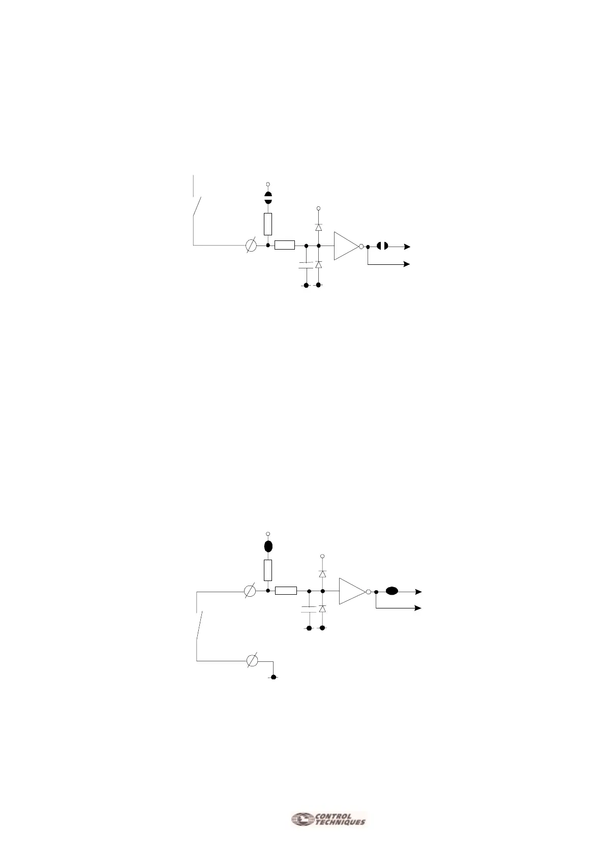
Enabling drive with Positive Logic
Enabling drive with positive logic. Solder link S12 and S13 normally open. Logic input min. 8V, max. 24Vdc.
Unconnected input = Not Enabled
Input to +V = Enabled
Enabling drive with Negative Logic
Enabling drive with negative logic. Solder link S12 and S13 closed.
Enable for input connected to GND.
Ving. < = 6V.
Unconnected input = Not Enabled
Input to GND = Enabled
10K
100nF
+5V
+Vcc
S1 2
S1 3
ENABLE
10K
100nF
+5V
S1 2
S1 3
ENABLE
 Loading...
