Safety
Information
Product
Information
Mechanical
Installation
Electrical
Installation
Getting
Started
Menu 0
Running
the motor
Optimisation Macros
Advanced
Parameters
Technical
Data
Diagnostics
UL Listing
Information
136 Unidrive User Guide
www.controltechniques.com Issue Number: 9
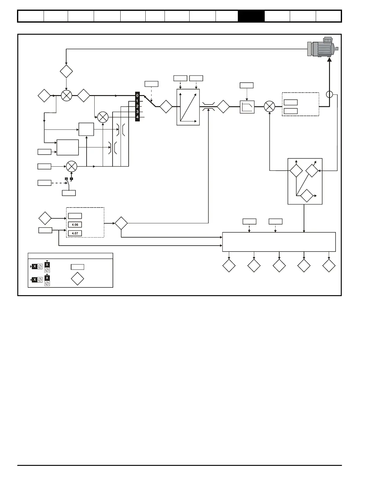
Figure 10-6 Menu 4 Closed-loop vector logic diagram
* For more information, please refer to section 10.22.3 Torque
Modes on page 183.
** For more information, please refer to section 10.22.5 Mains loss
modes on page 185.
4.04
Current
demand
4.12
Filter time
constant
Filter
+
3.04
+
3.01
3.02
4.08
4.09
10.0910.08
4.15 4.16
4.13
4.14
Current loop
P gain**
Current loop
I gain**
Current controller
4.18
11.32
5.07
4.05
Motoring
Regenerating
Current limits
Symmetrical
Drive rated
continuous
current
Motor rated
current
Speed
feedback
Final
speed
demand
+
Over-riding
current limit
3.05
Zero
speed
threshold
Speed loop
output
Torque reference
offset
Torqu e
reference*
Speed
over-ride
level
Coiler/uncoiler
speed
over-ride
level
+
Motor thermal
time constant
Motor protection
mode
At 100%
load
indicator
Current limit
active
indicator
5.07 5.10
Motor
rated
power
factor
Motor
rated
current
Active
current
Current
magnitude
Magnetising
current
4.02
4.20
- Active
current
(Amp)
- Percentage
torque
current
4.02
4.20
4.17
4.01
10.174.19
Motor
overload
accumulator
Motor current
overload alar
indicator
10.39
Braking energy
overload
indicator
Torque mode
selector*
4.11
4.10
To rq u e
reference
offset
enable
+
+
+
4.03
Torque
demand
0.XX
0.XX
Key
Read-write (RW)
parameter
Read-only (RO)
parameter
Input
terminals
Output
terminals
The parameters are all shown at their default settings