Safety
Information
Product
Information
Mechanical
Installation
Electrical
Installation
Getting
Started
Menu 0
Running
the motor
Optimisation Macros
Advanced
Parameters
Technical
Data
Diagnostics
UL Listing
Information
Unidrive User Guide 183
Issue Number: 9 www.controltechniques.com
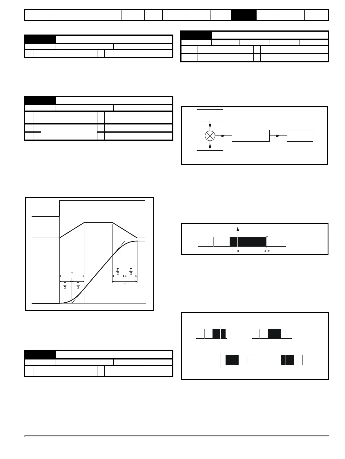
10.22.2 S ramps
Setting this parameter enables the S ramp function. S ramp is disabled
during deceleration using Standard ramp with P control (Pr 2.04 =
Stnd.Ct [2]). When the motor is accelerated again after decelerating in
standard ramp with P control the acceleration ramp used by the S ramp
function is reset to zero.
This parameter defines the maximum rate of change of acceleration/
deceleration that the drive will operate with. The default values have
been chosen such that for the default ramps and maximum speed, the
curved parts of the S will be 25% of the original ramp if S ramp is
enabled.
Since the ramp rate is defined in s/100Hz or s/1000rpm and the S ramp
parameter is defined in s
2
/100Hz or s
2
/1000rpm, the time T for the
'curved' part of the S can be determined from:
T = S ramp rate of change / Ramp rate
Enabling S ramp increases the total ramp time by the period T since an
additional T/2 is added to each end of the ramp in producing the S.
10.22.3 Torque Modes
Parameter for main torque reference. If connected to an analog input on
this drive this parameter is updated every 345µs for 3, 6 and 12kHz
switching frequency, and every 460µs for 4.5 and 9kHz switching
frequency. This does not apply to the analog inputs of the UD50
Additional I/O Small Option Module.
Open loop
If this parameter is 0 normal frequency control is used. If this parameter
is set to 1 the current demand is connected to the current PI controller
giving closed loop torque/current demand as shown below. The current
error is passed through proportional and integral terms to give a
frequency reference which is limited to the range -maximum frequency
to +maximum frequency as defined by Pr 1.06.
Closed loop
0: Speed control mode
The torque demand is equal to the speed loop output.
1: Torque control
The torque demand is given by the sum of the torque reference and the
torque offset, if enabled. The speed is not limited in any way, however,
the drive will trip at the overspeed threshold if runaway occurs.
2: Torque control with speed override
The output of the speed loop defines the torque demand, but is limited
between 0 and the resultant torque reference [Pr 4.08 (+ Pr 4.09 when
enabled)]. The effect is to produce an operating area as shown above if
the final speed demand and the resultant torque reference are both
positive. The speed controller will try and accelerate the machine to the
final speed demand level with a torque demand defined by the resultant
torque reference. However, the speed cannot exceed the reference
because the required torque would be negative, and so it would be
clamped to zero.
Depending on the sign of the final speed demand and the resultant
torque the four areas of operation shown here are possible. This mode
of operation can be used where torque control is required, but the
maximum speed must be limited by the drive. In this mode ramps are not
active whilst the drive is in the run state. When the drive is taken out of
the run state, but not disabled, the appropriate stopping mode is used. It
is recommended that only coast or stopping without ramps is used. If
ramp stop mode is used the drive changes to speed control mode to
2.06 S-ramps enable
RW Bit
Ú
0 or 1
Ö
0
2.07 S-ramp da/dt
RW Uni
OL
Ú
0 to 3,000.0
s
2
/100 Hz
Ö
3.1
VT
Ú
0 to 30.000
s
2
/1,000 rpm
Ö
1.5
SV
ÚÖ
0.03
4.08 Torque reference
RW Bi
Ú
Maximum current limit
% rated active current
Ö
0
Demanded
speed
Programmed
ramp rate
Rate of change
of S-ramp
acceleration
tim
4.11 Torque mode selector
RW Uni
OL
Ú
0 to 1
Ö
0
CL
Ú
0 to 4
Ö
0
4.13 Proportional gain
4.14 Integral gain
Current
demand
Active current
Frequency
reference
Speed
Current
4.08 (+ 4.09 when enabled)
+
na
spee
eman
+Resultant torque
−
Final speed demand
+Resultant torque
+Final speed demand
−
Resultant torque
−
Final speed demand
−
Resultant torque