Safety
Information
Product
Information
Mechanical
Installation
Electrical
Installation
Getting
Started
Menu 0
Running
the motor
Optimisation Macros
Advanced
Parameters
Technical
Data
Diagnostics
UL Listing
Information
188 Unidrive User Guide
www.controltechniques.com Issue Number: 9
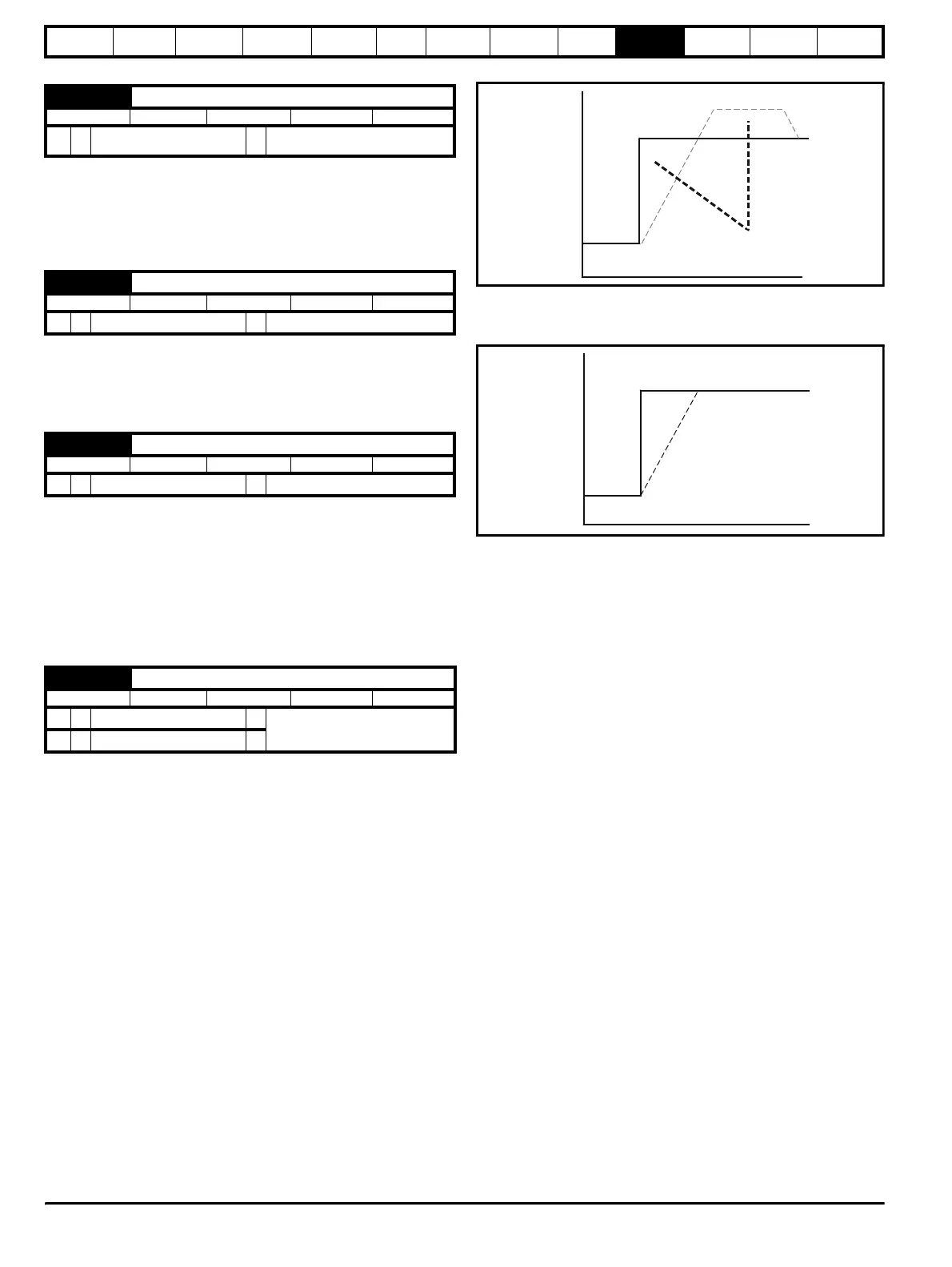
This parameter defines the rate at which the frequency is changed when
trying to synchronise the motor speed. Motors and loads with very low
inertias will require this parameter to be set low to ensure the speed is
detected, while motors and loads with large inertias may require the
parameter to be increased to prevent over voltage trips.
Defines the voltage applied during a spin start as a percentage of
voltage that would be applied in normal operation. Setting this value too
high causes the drive to current limit, setting it too low will give problems
detecting low motor speeds.
When the software has detected the motor speed it ramps the drives
output voltage from the level programmed in Pr 6.37 to its normal
operating voltage. This parameter determines the time interval for this
change in voltage. Setting the time too short will cause excessive current
transients in the machine as the voltage rises, while setting it too long
may cause the drive to lose synchronisation if the motor is decelerating
quite quickly.
10.22.8 Position loop modes
0 Position loop disabled
1 Rigid digital lock with digital Feed Forward
2 Rigid digital lock without digital Feed Forward
3 Non rigid digital lock with digital Feed Forward
4 Non rigid digital lock without digital Feed Forward
5 Orientate on stop command only
6 Orientate on stop command and when enabled
Sets the mode of operation of the position loop.
In rigid lock mode the position error is absolute relative to the time the
position loop is closed. This means that if the slave shaft is slowed down
due to excessive load, the target position will eventually be recovered by
running at a higher speed when the load is removed.
In non-rigid lock mode the position loop is only closed when the 'At
Speed' condition is met. This allows slippage to occur while the speed
loop is not satisfied.
Digital lock can be implemented without digital feed forward, where the
input frequency of the encoder being followed is too low to obtain a
smooth feed forward term from it. In this case the user can provide an
alternative speed reference to be used as the feed forward term and the
position loop will provide the velocity correction only. It should be noted
that if the alternative feed forward is not correct, the position loop will run
with a constant error to provide the difference between the feed forward
and the actual speed of the reference encoder. During relative jogging,
digital feed forward is always used because the feed forward term has to
be adjusted.
In order for the digital feed forward term to function in modes 1 and 3 the
hard speed reference must be enabled (Pr 3.20 = 1). The correction
term used in the feed forward modes is fed into the speed loop via the
hard speed reference in menu 3 (see block diagrams). If a non-rigid
mode is used and an independent correction term is required then this
must be routed to the hard speed reference (Pr 3.19) by the user.
Two orientation modes are selectable. In mode 5, the drive orientates
following a stop command with orientation stop enabled (see Pr 6.01
Stop mode). Mode 6 operates the same as mode 5 but in addition the
drive always orientates when it is enabled providing that the 'Hold zero
speed' parameter is set (Pr 6.08). This ensures that the spindle is always
in the same position following the drive being enabled.
When orientating from a stop command the drive goes through the
following sequence:
1. Ramps are enabled and the motor is decelerated or accelerated to
the speed limit programmed in Pr 13.10 in the direction the motor
was previously running.
2. When the speed set in Pr 13.10 is reached, ramps are disabled and
the motor continues to rotate until the position is found to be close to
the target position. At this point the speed demand is set to 0 and the
position loop is closed.
3. When the absolute value of speed is less than 2 rpm and the
position is within the window defined by Pr 13.12, the orientation
complete signal is given.
6.10 Spinning motor ramp rate
RW Uni
OL
Ú
0 to 25.0 s/100Hz (seconds
per 100Hz)
Ö
5.0
6.37 Spinning motor start-voltage
RW Uni
OL
Ú
0 to 100 % (of normal voltage)
Ö
25.0
6.38 Spinning motor voltage rate
RW Uni
OL
Ú
0 to 2.5 s
Ö
0.25
13.08 Position loop mode selector
RW Uni
OL
Ú
0 to 2
Ö
0
CL
Ú
0 to 6
Ö
Reference
Actual
Speed
Equal Areas
t
Reference
Actual
Speed