Safety
Information
Product
Information
Mechanical
Installation
Electrical
Installation
Getting
Started
Menu 0
Running
the motor
Optimisation Macros
Advanced
Parameters
Technical
Data
Diagnostics
UL Listing
Information
24 Unidrive User Guide
www.controltechniques.com Issue Number: 9
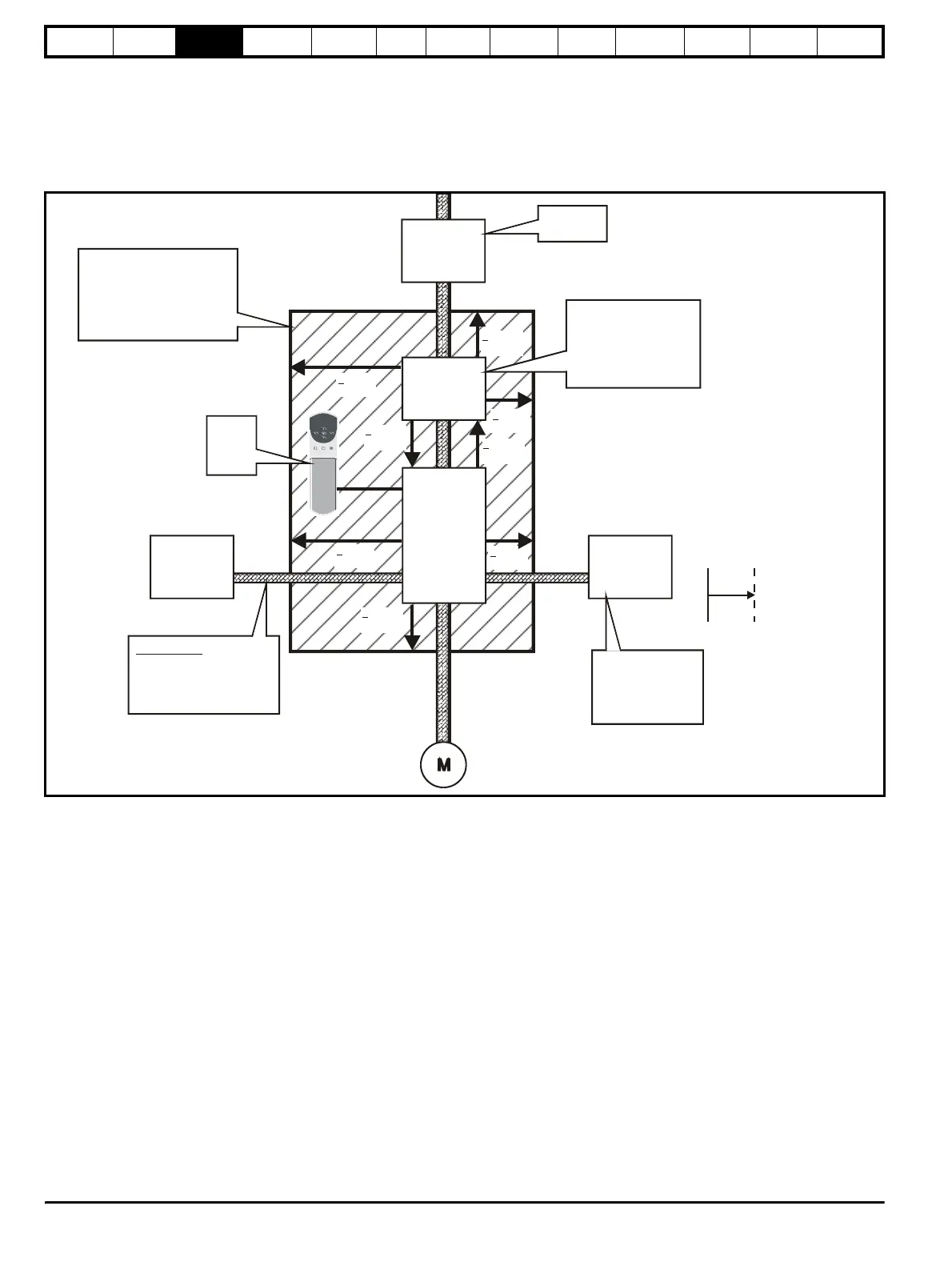
3.7 Enclosure
3.7.1 Enclosure Layout
Please observe the clearances in the diagram below taking into account
any appropriate notes for other devices / auxiliary equipment when
planning the installation.
Figure 3-14 Enclosure layout
3.7.2 Enclosure sizing
1. Add the dissipation figures from section 11.1.2 Power dissipation (all
versions) on page 191 for each drive that is to be installed in the
enclosure.
2. If an RFI filter is to be used with each drive, add the dissipation
figures from section 11.2.1 Ratings on page 197 for each RFI filter
that is to be installed in the enclosure.
3. If the braking resistor is to be mounted inside the enclosure, add the
average power figures for each braking resistor that is to be installed
in the enclosure.
4. Calculate the total heat dissipation (in Watts) of any other equipment
to be installed in the enclosure.
5. Add the heat dissipation figures obtained above. This gives a figure
in Watts for the total heat that will be dissipated inside the enclosure.
Calculating the size of a sealed enclosure
The enclosure transfers internally generated heat into the surrounding
air by natural convection (or external forced air flow); the greater the
surface area of the enclosure walls, the better is the dissipation
capability. Only the surfaces of the enclosure that are unobstructed (not
in contact with a wall or floor) can dissipate heat.
Calculate the minimum required unobstructed surface area A
e
for the
enclosure from:
Where:
A
e
Unobstructed surface area in m
2
(1m
2
= 10.8 ft
2
)
T
ext
Maximum expected ambient temperature in
o
C outside the
enclosure
T
int
Maximum permissible ambient temperature in
o
C inside the
enclosure
P Power in Watts dissipated by all heat sources in the
enclosure
k Heat transmission coefficient of the enclosure material
in Wm
2
/
o
C
Control
module
(size 5
only)
Locate
as required
AC supply
contactor and
fuses or MCB
Optional
RFI filter
Drive
> 100mm
(3.937in)
Note: for EMC compliance
1) A separate RFI filter is
required for each drive
2) Power cabling must be
at least 100mm (4in) from
the drive in all directions
Note: Footprint RFI filters
are available for Unidrive
frame sizes 1 and 2
Indicates minimu
clearance required
from device
Ensure minimum clearances
are maintained for the
drive and RFI filter
Forced or convection air-flow
must not be restricted by any
object or cabling
Signal cables
Plan for all signal cables
to be routed at least
300mm (12in) from the drive
and any power cable
Controller
Locate as close to
the drive as possible
(to keep the cable
as short as possible)
respecting the minimum
clearances
Locate resistor
external to cubicle
(preferably near to
or at the top of the
cubicle)
Optional
braking resistor
and overload
> 5mm
(0.197in)
> 5mm
(0.197in)
> 100mm
(3.937in)
> 100mm
(3.937in)
> 5mm
(0.197in)
> 5mm
(0.197in)
> 100mm
(3.937in)
A
e
P
kT
int
T
ext
–()
-----------------------------------
=