Safety
Information
Product
Information
Mechanical
Installation
Electrical
Installation
Getting
Started
Menu 0
Running
the motor
Optimisation
Macros
Advanced
Parameters
Technical
Data
Diagnostics
UL Listing
Information
108 Unidrive User Guide
www.controltechniques.com Issue Number: 9
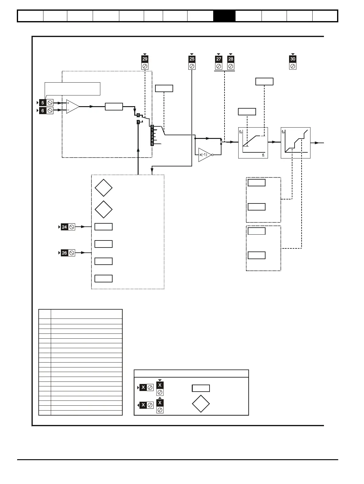
Figure 9-2 Macro 2 Motorised potentiometer logic diagram
Reference selection
Frequency/speed ref. 1
DOWN
RUN
FORWARD
RUN
REVERSE
RESET and
MOT. POT. RESET
0.24
Analog input 1
mode selector
Motorized pot.
output indicator
0.05
Reference
selector
29
MOTORIZED
POT. ENABLE
Minimum
frequency/
speed clamp
0.01
0.02
0.20
0.21
0.22
0.23
Skip frequency/
speed 1
Skip freq./speed
band 1
Skip frequency/
speed 2
Skip freq./speed
band 2
Skip
frequencies/
speeds
UP
OL> EXTERNAL TRIP
CL> DRIVE ENABLE
Motorized pot.
zero-start select
0.27
0.28
0.29
0.30
Motorized pot.
bipolar select
Motorized pot. rate
Motorized pot.
output scale factor
Motorized pot.
reset indicator
0.26
0.25
6
6
0.XX
0.XX
Key
Read-write (RW)
parameter
Read-only (RO)
parameter
Input
terminals
Output
terminals
Pr Function
0.11 Pre-ramp reference
0.12 Post-ramp reference
0.13 Motor active-current
0 14 Jog reference (not used)
0.15 Ramp mode
0.16 Stop mode
0.17 Status relay
0.18 S-ramp
0.19 S-ramp da/dt
0.20 Skip frequency/speed 1
0.21 Skip freq./speed band 1
0.22 Skip frequency/speed 2
0.23 Skip freq./speed band 2
0.24 Analog input 1 mode
0.25 Motorised pot. reset
0.26 Motorised pot. output
0.27 Motorised pot. zero-start
0.28 Motorised pot. Bipolar
0.29 Motorised pot. rate
0.30 Motorised pot.output scale factor
selector
selector
invert
enable
selector
indicator
indicator
select
select
Menu 0 changes from default configuration