10 Unidrive M300/HS30 Quick Start Guide
Issue Number: 7
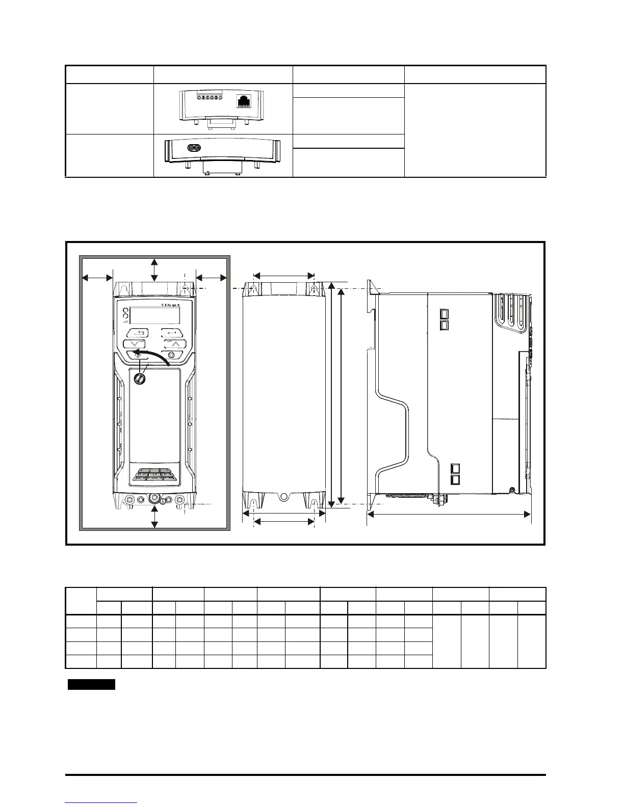
Table 2-2 Adaptor Interface (AI) option module identification
3 Mechanical installation
The drives can be panel mounted with 0 mm space between the drives. For further information on
mechanical installation refer to the Power Installation Guide.
To remove the terminal cover, use a flat bladed screwdriver to rotate the terminal cover locating clip
by approximately 30° in a counter clockwise direction, and then slide the cover down.
Type Option module Name Further Details
Communications
AI-485 Adaptor
See Control User Guide
AI-485 24V Adaptor
Backup
AI-Backup Adaptor
AI-Smart Adaptor
Drive
Size
HWD M1M2∅ AB*
mm in mm in mm in mm in mm in mm in mm in mm in
1 160 6.30 75 2.95 130 5.12 143 5.70 53 2.08 5 0.2
0 0.00 100 3.93
2 205 8.07 75 2.95 150 5.91 194 7.63 55 2.17 5 0.2
3 226 8.90 90 3.54 160 6.30 215 8.46 70.7 2.80 5 0.2
4 277 10.91 115 4.53 175 6.89 265 10.43 86 3.40 6 0.23
A minimum clearance of 100 mm (3.94 in) above and below Frame 01 to 04 products is
required for applications where the product is subjected to rated load and rated ambient
temperature.