Unidrive M100/M101/M200/M201/M300 Step By Step Guide 5
Issue Number: 1
English
French German Italian Spanish
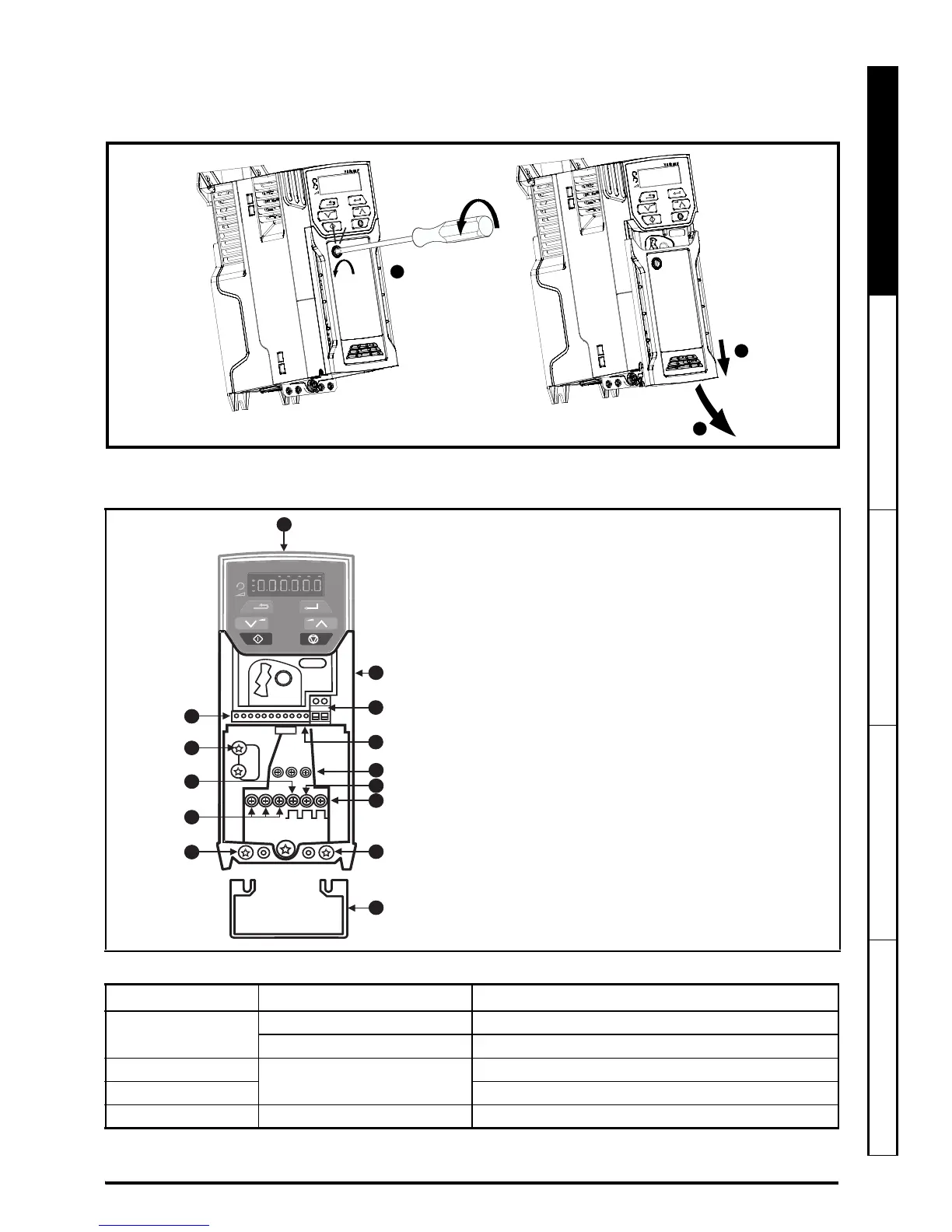
STEP 6: Remove the terminal cover
1. Using a flat bladed screwdriver, turn the terminal cover locking clip anti-clockwise by approximately 30°.
2. Slide the terminal cover down.
3. Remove terminal cover in direction shown.
STEP 7: Identify the features of the drive
Figure 7-1 Feature diagram (size 2 shown)
Table 7-1 Recommended torque settings
Model size Terminal block description Torque settings
All
Control terminals 0.2 N m (0.15 Ib ft)
Relay terminals 0.5 N m (0.37 Ib ft)
1
Power terminals
0.5 N m (0.37 Ib ft)
2, 3, 4 1.4 N m (1.03 Ib ft)
All Ground terminals 1.5 N m (1.10 Ib ft)
Key
1. Rating label (on side of drive)
2. Identification label
3. Relay connections
4. Control connections
5. Braking terminal
6. Internal EMC filter screw*
7. DC bus +
8. DC bus -
9. Motor connections
10. AC supply connections
11. Ground connections
12. Safe Torque Off terminals (STO)**
13. Cable bracket to screw onto ground
terminals (11).
* Before removing the screw, refer to section 4.7.2
in the Power Installation Guide.
** Unidrive M300 only.