6 Unidrive M100/M101/M200/M201/M300 Step By Step Guide
Issue Number: 1
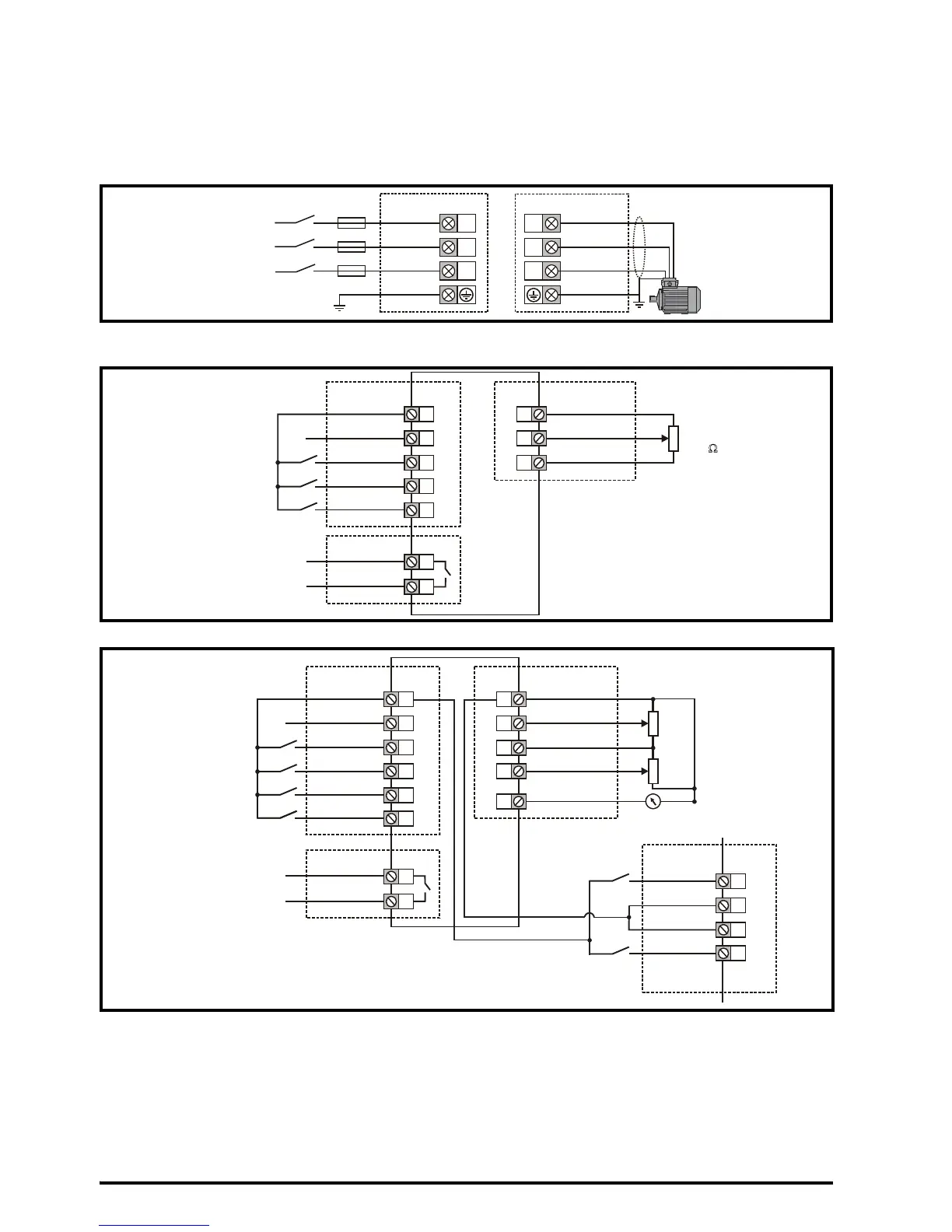
STEP 8: Wire the drive up
M100/M200/M300: The wiring diagram is for use with the default drive configuration (Pr 05 set to AV) which is
frequency control via Analog Input 1 (0-10 V) or Analog Input 2 (0-10 V) selected by terminal 14.
M101/M201: The default setting uses the onboard Speed Ref Potentiometer rather than the analog input for the
frequency reference (only the drive enable terminal is required).
Figure 8-1 Power terminal connections
* With a 1 ph supply, the supply should be connected to L1 and L3.
Figure 8-2 Unidrive M100/M101 control terminal connections
Figure 8-3 Unidrive M200/M201/M300 control terminal connections
** Not required on Unidrive M101 and M201 since the Speed Ref Potentiometer is already on the product. The Run/
Stop commands are given from the keypad and if reverse direction is needed, the user should set Pr 17 to On.
*** Unidrive M300 uses Safe Torque Off (drive enable) inputs and terminal 11 is unassigned.
**** 250 Vac maximum (UL class 1).
Refer to section 4.4 in the Quick Start Guide for information and wiring diagrams for alternative configurations.
An external braking resistor can be connected if required. Refer to section 4.5.1 in the Power Installation Guide
for further details.