EasyManuals Logo

Controls CX Series User Manual

Controls CX Series
62 pages
To Next Page IconTo Next Page
To Previous Page IconTo Previous Page
Page #61 background imageLoading...
Page #61 background image
60
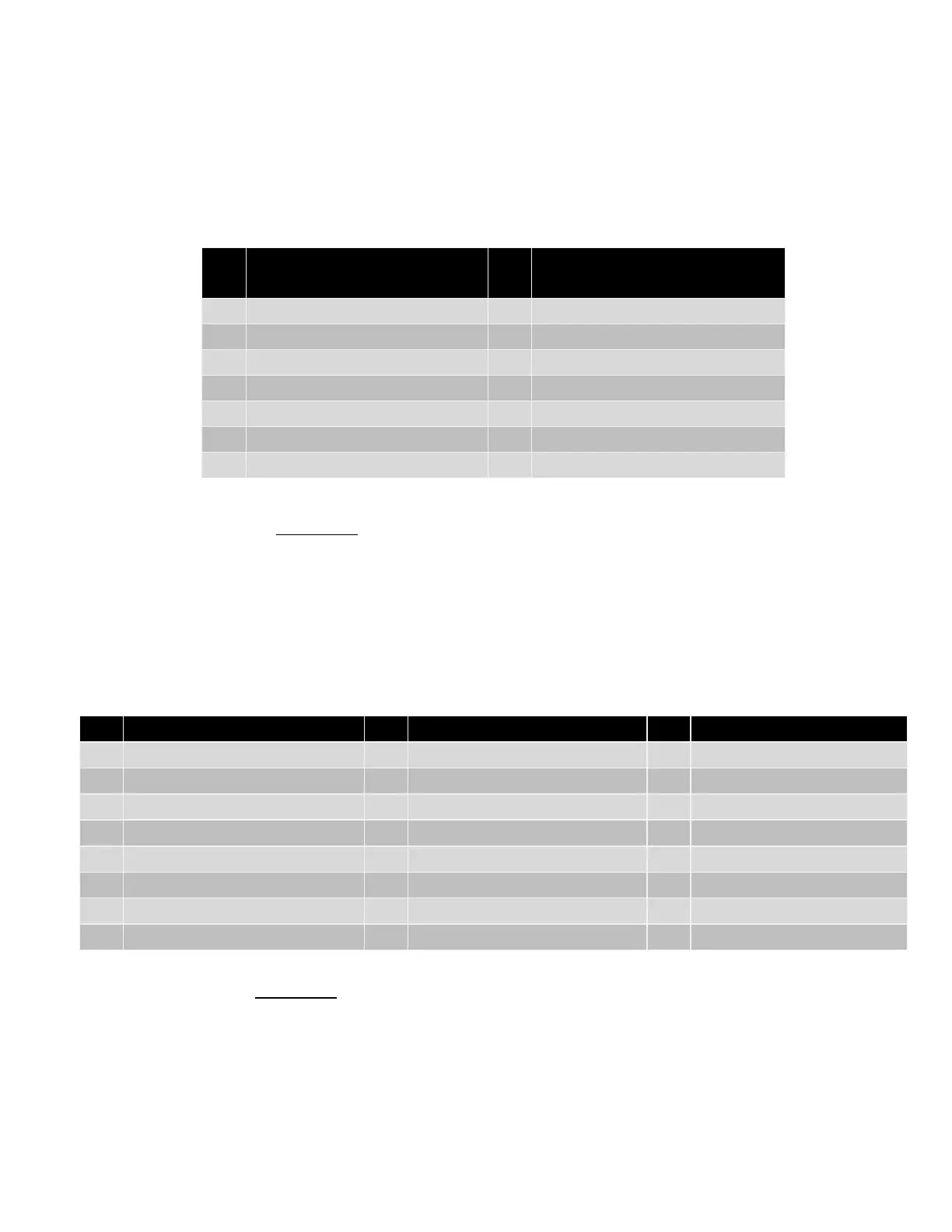
MODULE PRIMARY CONNECTOR
Ampseal 776273-1 Mating Plug with 770854-3 Sockets
Pin
Function
Pin
Function
1
ECU Power / Fuel Solenoid
8
J1939 Low
2
Horn Signal
9
Common B Positive
3
Crank Signal
10
Manual Crank Detect
4
Battery Positive
11
Battery Positive
5
Crank Signal
12
Battery Negative
6
Common B Positive
13
Fuel Level Sender
7
J1939 High
14
High Float Input
MODULE SECONDARY CONNECTOR
Ampseal 770680-1 Mating Plug with 770854-3 Sockets
Pin
Function
Pin
Function
Pin
Function
1
Relay Output 5
9
Relay Common 5 & 6
16
Relay 6 Contact
2
Oil Pressure Sender
10
Temperature Sender
17
Low Float Input
3
Sump Level Transducer
11
Suction Transducer
18
Digital Input 3
4
Discharge Press Transducer
12
Flow Meter Transducer
19
Digital Input 4
5
Speed (MPU) Input*
13
MODBUS A
20
Digital Input 5
6
Digital Input 8
14
MODBUS B
21
Digital Input 6
7
Digital Input 9
15
Relay Common 7 & 8
22
Digital Input 7
8
Relay Output 7
23
Relay Output 8
CAUTION:
Max Load for Relays 1 and 3 is 5 amps each
Max Load for Fuel and Crank circuits is 10 amps each
CAUTION:
Max Load for Relays 5, 6, 7 and 8 circuits is 5 amps each

Questions and Answers:

Question and Answer IconNeed help?

Do you have a question about the Controls CX Series and is the answer not in the manual?

Controls CX Series Specifications

General IconGeneral
BrandControls
ModelCX Series
CategoryControl Unit
LanguageEnglish

Related product manuals