EasyManua.ls Logo

Controls MX Series User Manual

Controls MX Series
59 pages
To Next Page IconTo Next Page
Page #1 background imageLoading...
Page #1 background image
PRODUCT MANUAL
ENGINE CONTROL MODULE
MX SERIES
Part Number: MX-500-AS through MX-505-AS
Revision: V1.0
Engine Type: Electronic and Mechanical Engines
______________________________________________________________________________________________________________________________________
Question and Answer IconNeed help?

Do you have a question about the Controls MX Series and is the answer not in the manual?

Controls MX Series Specifications

General IconGeneral
BrandControls
ModelMX Series
CategoryControl Unit
LanguageEnglish

Summary

INSTALLATION

MOUNTING LOCATION

Guidelines for properly positioning the control panel to ensure longevity and ease of use.

MANUAL OPERATION

POWER UP

Procedure for powering on the control module, including display initialization and verification.

CONTROLLER MODES

MANUAL OFF

Description of the module's state after powering down the engine or the system.

MANUAL STARTING

RUN BUTTON

Instructions for initiating engine start sequence using the RUN button and related display messages.

SAFETY BYPASS

ENGINE RUNNING

SPEED CONTROL - ELECTRONIC ENGINES

SPEED CONTROL - MECHANICAL ENGINES

STOPPING THE ENGINE

SPEED CONTROL OPTIONS

ELECTRONIC ENGINE SPEED CONTROL

Control of engine speed via J1939 TSC1, including requested speed adjustments using up/down arrows.

REQUESTED SPEED VERSUS ACTUAL SPEED

TSC VERNIER THROTTLE

TSC BUMP SPEED

TSC MULTISTATE THROTTLE

TSC HI-LO MOMENTARY THROTTLE

FLEX-ANALOG THROTTLE

MODBUS THROTTLE

SPEED / TORQUE LIMIT

COOPERATIVE THROTTLE

TWIST THROTTLE KNOB

DISPLAY CONFIGURATION

GRAPHICAL DISPLAY

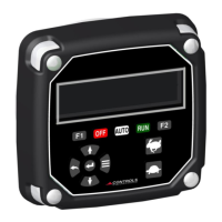
Description of the 3.2" OLED display with 256x64 resolution, known for readability and wide temperature range.

DISPLAY LAYOUT

Defines the display into 10 sections, numbered 1-8 for parameters, 9 for annunciation, and 10 for the clock.

DISPLAY CUSTOMIZATION

PROTECTION OPTIONS

ECU SAFETY SHUTDOWNS AND WARNINGS

ECU's primary control over engine operation, handling tolerance and taking actions like derating or shutdown.

MODULE SAFETY SHUTDOWNS AND WARNINGS

LOW POWER (SLEEP) MODE

OTHER MODULE FUNCTIONALITY

STANDARD FEATURES

The control panel has many options that can be configured, enabled or selected that will enhance the operation of the equipment.

CUSTOM SPLASH SCREEN

The control panel can be programmed to customize the initial display screen when powered up.

SENDER FAILURE

The control panel can detect when a local sender for a parameter is not present, indicating dashes on display.

AUDIBLE HORN

SHUTDOWN OVERRIDE

AUTO START OPERATION

GENERAL INFORMATION

MX Series modules offer high configurability for auto start applications via digital input, Modbus, CANbus, or scheduler.

AUTO START MODE

SCHEDULER AUTO START

AUTOMATIC SINGLE SPEED CONTROL MODE

FLOAT OPERATION

SINGLE FLOAT SYSTEM

Basic level control using a single float device with contact closure for applications without critical start/stop points.

DUAL FLOAT SYSTEM

More precise level control using two floats (low and high limits) for stringent requirements or turbulent fluids.

TRANSDUCER INSTALLATION

GENERAL

Guidelines for using transducers with analog channels for pump inlet and outlet pressure monitoring.

MAIN MENU ACCESS

MAIN MENU TOPICS

ACTIVE ENGINE FAULT CODES

Allows viewing trouble codes generated by the engine's ECU, typically indicated by a yellow warning lamp.

STORED ENGINE FAULT CODES

The module stores the engine's ECU fault codes, allowing users to view and clear them.

ENGINE PARAMETERS

EMISSIONS PARAMETERS

PUMP PARAMETERS

OPERATION EVENT LOG

ALARMS EVENT LOG

ENGINE IDENTIFICATION

MODULE INFORMATION

MODULE PROGRAMMING

PROGRAMMING OPTIONS

Overview of the two available methods for programming the control panel: onboard menu or PC-based CI Station.

PC BASED PROGRAMMING

Details on the CI Station kit, including its components and use for saving and reusing configurations.

MODULE BASED PROGRAMMING

CONTROLLER SETUP

PASSWORD ENTRY

Screen for entering a password to enable configuration changes; navigation is possible without one.

SETUP MENU

QUICK SETUP

ENGINE PARAMETER CONFIGURATION

PUMP PARAMETER CONFIGURATION

SCHEDULER CONFIGURATION

INPUT CONFIGURATION

OUTPUT CONFIGURATION

THROTTLE CONFIGURATION

ENGINE SAFETY CONFIGURATION

PUMP SAFETY CONFIGURATION

MODULE CONFIGURATION

DISPLAY CONFIGURATION

CAN CONFIGURATION

AUTO START CONFIGURATION

BATTERY RECHARGE CONFIGURATION

MAINTENANCE CONFIGURATION

EMISSION CONFIGURATION

MODBUS CONFIGURATION (OPTIONAL)

CLUTCH CONFIGURATION

CLOCK SETUP

MODULE CONNECTORS

DISPLAY CONNECTOR (STANDARD)

DISPLAY CONNECTOR (MODBUS OPTION)

DISPLAY CONNECTOR (KUBOTA Analog Pedal Sensor OPTION)

DISPLAY CONNECTOR (SINGLE TRANSDUCER OPTION, MECH OR ELEC ENGINE)

DISPLAY CONNECTOR (DUAL TRANSDUCER OPTION, ELECTRONIC ENGINE)

DISPLAY CONNECTOR (FOUR DIGITAL INPUTS, ELECTRONIC ENGINE)

WARRANTY

Related product manuals